Double-hand disinfection device for hospital nurses

A technology for nursing staff and disinfection devices, applied in the direction of medicine and equipment, can solve the problems of inconvenience of carrying disinfectant, inconvenience of timely disinfection, residual bacteria on hands, etc. Effect

Active Publication Date: 2021-02-23
HEILONGJIANG NONGKEN VOCATIONAL COLLEGE +1
View PDF3 Cites 0 Cited by
  • Summary
  • Abstract
  • Description
  • Claims
  • Application Information

AI Technical Summary

Problems solved by technology

[0004] The purpose of the present invention is to provide a hands disinfection device for hospital nurses, which solves the problem that in the prior art, the nurses need to touch the disinfectant bottle to clean and disinfect, resulting in unclean cleaning and residual bacteria on the hands. Not easy to carry around, not easy to disinfect in time

Method used


Image

  • Double-hand disinfection device for hospital nurses
  • Double-hand disinfection device for hospital nurses
  • Double-hand disinfection device for hospital nurses

Examples


Embodiment 2

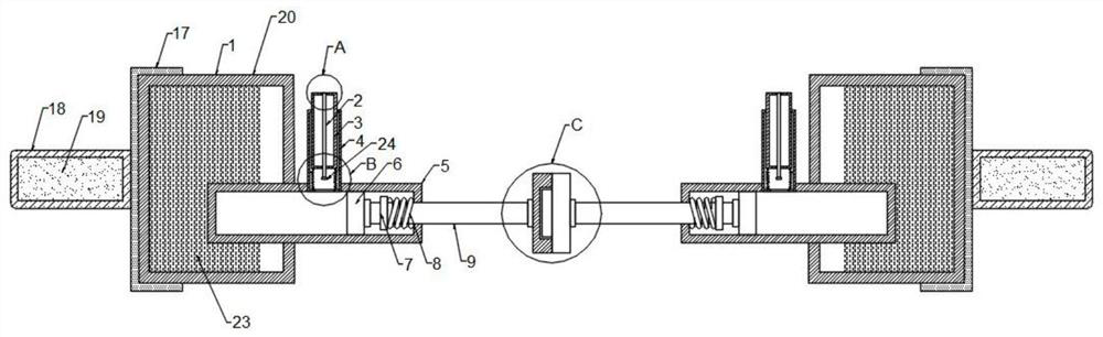
[0031] refer to figure 1 and Figure 4-6 , the disinfection mechanism 20 also includes a fixed rod 24 and a push rod 2, the two ends of the fixed rod 24 are fixedly connected with the bottoms on both sides of the inner side of the connecting pipe 4, and the center of the fixed rod 24 top is fixedly connected with a matching liquid outlet 12 The ejector rod 2 is used, and the ejector rod 2 is located directly below the liquid outlet hole 12, and the difference between the diameter of the liquid outlet hole 12 and the diameter of the ejector rod 2 is 0.2mm. Specifically, when the disinfectant 23 is not pumped, the ejector rod Rod 2 is inserted in the outlet hole 12 to prevent the disinfectant 23 from flowing out from the outlet hole 12. When the disinfectant 23 is extracted, the outlet hole 12 leaves the push rod 2. When there is no disinfectant 23 in the outlet pipe 3 At this time, the two second compression springs 10 pull the liquid outlet pipe 3 back, and the liquid outlet ...

Embodiment 3

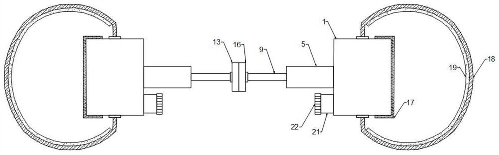
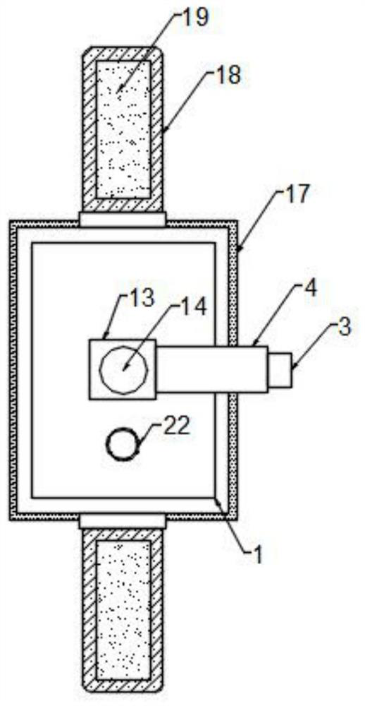
[0033] refer to Figure 1-3 , The disinfection mechanism 20 also includes a sponge pad 17, one side of the sponge pad 17 is fixedly connected to the side of the disinfectant box 1 away from the suction tube 5. Disinfection mechanism 20 also comprises heat-insulating sheet 19, and one side of heat-insulating sheet 19 is fixedly connected with the inner side of elastic ring belt 18, specifically, by arranging sponge pad 17 and heat-insulating sheet 19, sponge pad 17 prevents nursing staff from wearing elastic ring belt At 18 o'clock, the disinfectant solution box 1 causes damage to the nursing staff's wrist, protects the wrist, and the thermal insulation sheet 19 provides temperature to the nursing staff's wrist, activates menstrual blood, prevents the nursing staff's wrist from freezing, and is not convenient for nursing.


PUM


Abstract

The invention relates to the technical field of hand disinfection, in particular to a double-hand disinfection device for hospital nurses, and solves the problems that in the prior art, nurses can clean and disinfect the hands only by touching a disinfectant bottle, so that the hands are not cleaned thoroughly, bacteria remain on the hands, and existing disinfectants are inconvenient to carry, andtimely disinfection is not convenient. The double-hand disinfection device for hospital nurses comprises two disinfection mechanisms, the two disinfection mechanisms are correspondingly and fixedly connected with a first baffle and a second baffle correspondingly, a clamping groove is formed in one side of the first baffle, a clamping block used in cooperation with the clamping groove is arrangedon one side of the second baffle, the clamping groove is in clearance fit with the clamping block, and the two disinfection mechanisms are symmetrically arranged relative to the joint of the clampinggroove and the clamping block. According to the double-hand disinfection device for hospital nurses, nurses can clean and disinfect hands without touching the disinfectant bottle, residual bacteria are prevented, the double-hand disinfection device for hospital nurses is convenient to carry, and timely disinfection is convenient.

Description

technical field [0001] The invention relates to the technical field of hand disinfection, in particular to a hand disinfection device for hospital nurses. Background technique [0002] Hospitals refer to medical institutions that provide necessary medical examinations, treatment measures, nursing techniques, reception services, rehabilitation equipment, medical transportation and other services for patients in accordance with laws, regulations and industry norms, with the main purpose of saving lives and helping the wounded. The hands of nursing staff in the hospital need to be kept clean frequently so as to facilitate the care of patients. At present, when the nursing staff cleans and disinfects their hands, they often use medical disinfectant to clean their hands, and at the same time, use a cleaning brush to scrub their hands , and then complete hand cleaning and disinfection. [0003] However, the nursing staff need to touch the medical disinfectant bottle with their ha...

Claims


Application Information

Patent Timeline
Patent Type & Authority Applications(China)
IPC IPC(8): A61M35/00
CPCA61M35/10
Inventor 王慧颖王云飞王欢安娜潘彦彦程姗姗计仁军王凤荣陈焕芬张春霞张飞宇宁文帅侯媛媛郭佳张丽白雪
Owner HEILONGJIANG NONGKEN VOCATIONAL COLLEGE
Why Eureka
Try Eureka