Web combined type printing equipment and working method thereof

A printing equipment and combined technology, applied in the field of web combined printing equipment, can solve the problems of lack of winding mechanism and low efficiency

Inactive Publication Date: 2021-02-23
张彪
View PDF1 Cites 0 Cited by
  • Summary
  • Abstract
  • Description
  • Claims
  • Application Information

AI Technical Summary

Problems solved by technology

The above-mentioned patents have the following disadvantages: the above-mentioned equipment is designed for the vibration that may occur in printing, but the vibration of the web during the printing process is not reflected in the contact between the overall equipment and the ground, especially in the process of rewinding the web. Solve the winding work inside the equipment, but the above-mentioned equipment lacks a winding mechanism for the paper tube, and the efficiency is not high

Method used


Image

  • Web combined type printing equipment and working method thereof
  • Web combined type printing equipment and working method thereof
  • Web combined type printing equipment and working method thereof

Examples


Embodiment 1

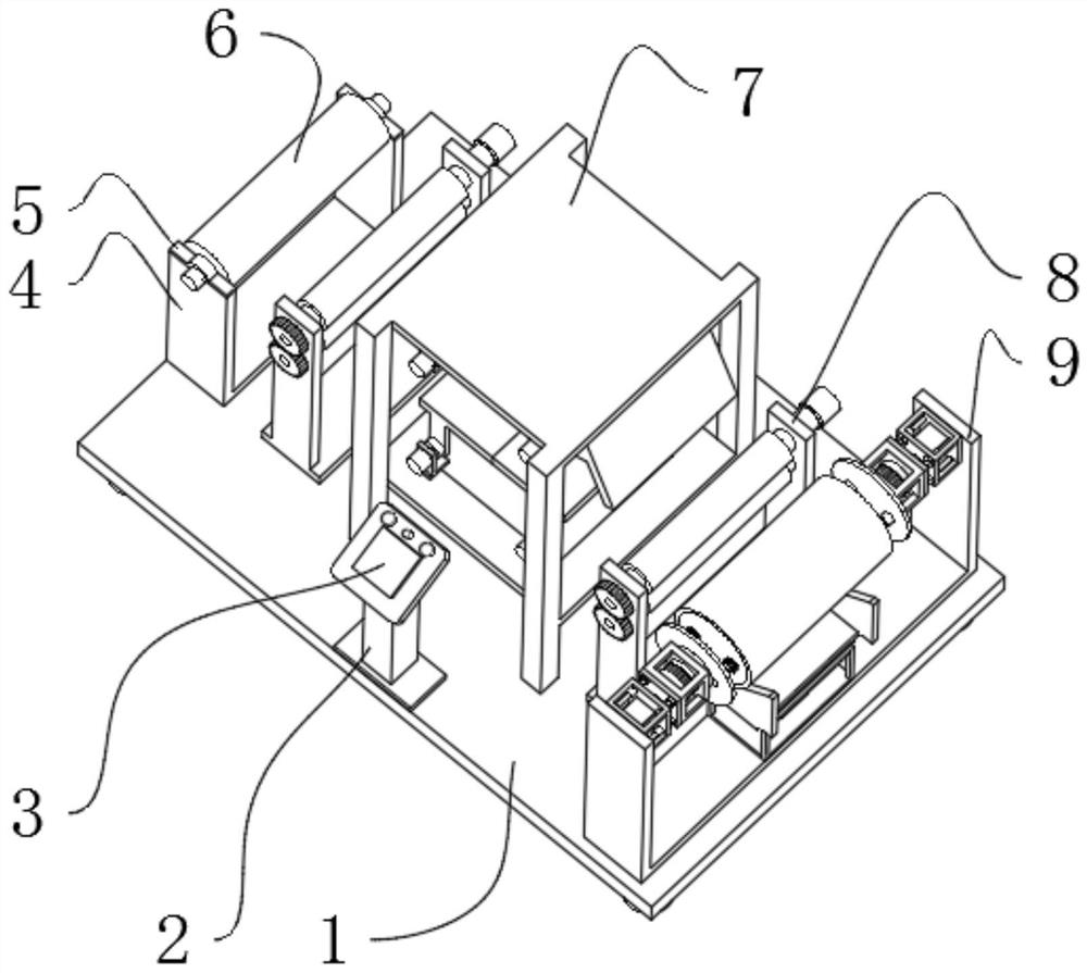
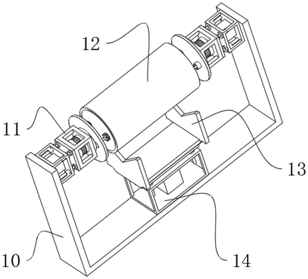
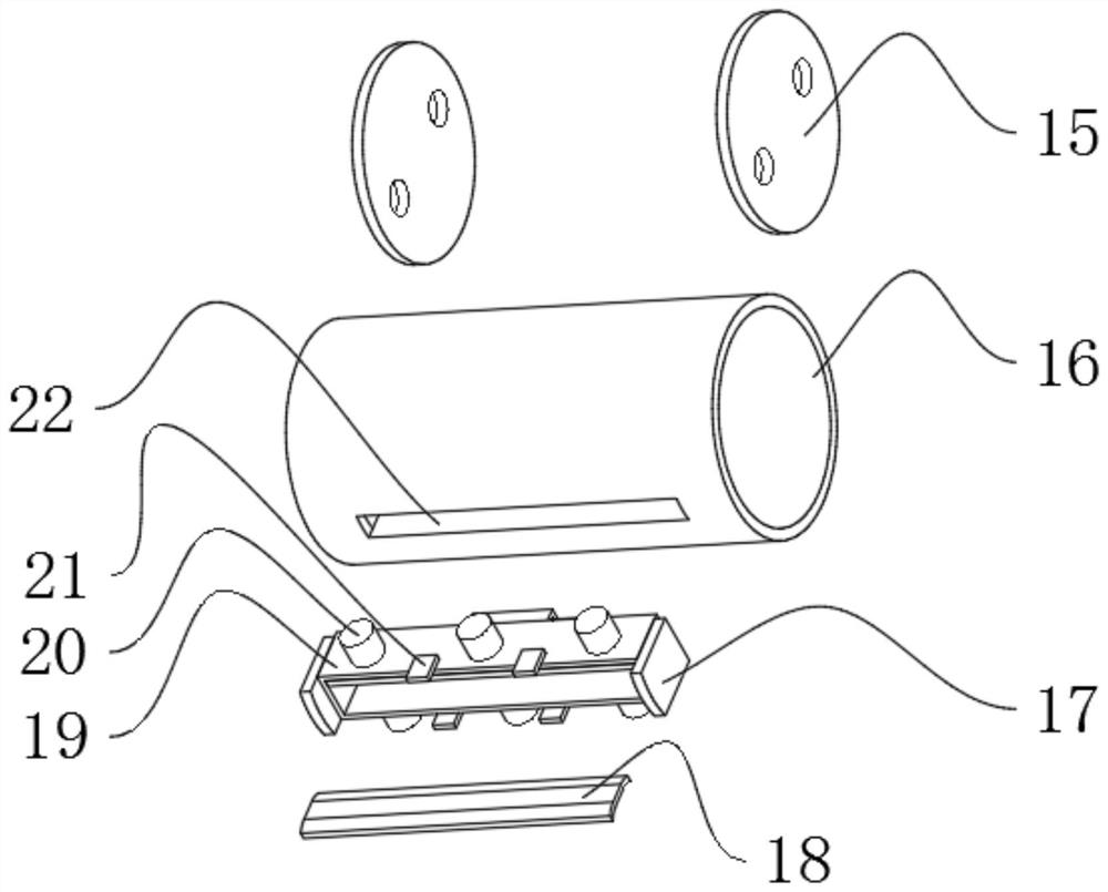
[0041] A web combined printing equipment, such as Figure 1-7 As shown, it includes the base plate 1, the top outer wall of the base plate 1 is fixedly connected with a printing support 7, and the printing support 7 is provided with printing components inside. The number of printing components is two groups, and they are installed in opposite directions. The drive assembly 8 and the winding mechanism 9, the winding mechanism 9 includes a winding support 10 and a reel assembly 12, the outer wall of the bottom of the rolling support 10 is fixedly connected to the outer wall of the top of the bottom plate 1, and the inner walls of both sides of the rolling support 10 are fixedly connected There is a rotary assembly 11, the outer wall of one side of the rotary assembly 11 is fixedly connected with a plunger assembly 27, the reel assembly 12 is fixedly connected to the outer wall of the plunger assembly 27, the reel assembly 12 includes a reel 16 and a cover plate 15, and the cover ...

Embodiment 2

[0046] A working method of web combined printing equipment, such as Figure 1-7 As shown, its method of use includes the following steps;

[0047] S1: place the raw material; place the raw material cylinder 6 wrapped with the raw material paper roll on the raw material support 4, and fasten the crimping plate 5;

[0048]S2: traction and fixation; the traction paper head passes through the first driving assembly 8, then passes through the printing support 7, then passes through the second driving assembly 8, and finally is fixed on the winding assembly 12;

[0049] S3: clamp the terminal; insert the end of the raw paper between the splints 18, and then start the clamping cylinder 20 to drive the splint 18 to clamp the paper;

[0050] S4: printing; when the paper needs to be printed on the front side, the closing plate 37 of one group of printing components is opened, the printing template 38 is pushed out, and the printing work is carried out, while the closing plate 37 of the...


PUM


Abstract

The invention discloses web combined type printing equipment and a working method thereof, and relates to the technical field of web printing. The problem that existing equipment is lack of a windingmechanism is solved. The equipment comprises a bottom plate; a printing support is fixedly connected to the outer wall of the top of the bottom plate; two sets of printing assemblies are arranged in the printing support and installed in the opposite directions; and a driving assembly and a winding mechanism are fixedly connected to the outer wall of the top of the bottom plate. The working methodof the equipment comprises the following steps of raw material placing, traction fixing, terminal clamping, printing, winding work and material taking. By arranging the winding mechanism and a windingdrum assembly arranged in the winding mechanism, a paper end box can be repeatedly used; the winding drum can achieve load reduction; damage caused by carrying of a clamping air cylinder in the transferring process is avoided; and clamping is achieved through the paper end box, and the danger of manual winding can be avoided.

Description

technical field [0001] The invention relates to the technical field of web printing, in particular to a web combined printing device and a working method thereof. Background technique [0002] In the web printing process, the winding of the paper cylinder requires professional equipment, but the existing combined printing equipment often ignores the winding of the paper cylinder, and most of them use manual methods, which makes the winding efficiency low and affects the entire The production beat of the web. [0003] After searching, the Chinese patent application number is 201710558182.8, which discloses a web combined printing equipment, including a body, the bottom of the body is fixedly connected with a power box, and both sides of the bottom of the power box are fixedly connected with The bottom of the supporting leg is movably connected with a moving wheel through a first rotating shaft, and the inner cavity of the power box is provided with a movable plate. The abov...

Claims


Application Information

Patent Timeline
Patent Type & Authority Applications(China)
IPC IPC(8): B65H75/28B65H19/30B65H20/02B65H18/02B65H18/10B41F17/00
CPCB41F17/00B65H18/028B65H18/10B65H19/30B65H20/02B65H75/28
Inventor 张彪
Owner 张彪
Why Eureka
Try Eureka