
Low-stress optical fiber cable take-up and pay-off device

A cable retracting device and cable retracting technology, applied in the field of optical cables, can solve problems such as increased cable wear and interference

Inactive Publication Date: 2021-02-23
广州大鹏机械设计有限公司
View PDF0 Cites 2 Cited by
  • Summary
  • Abstract
  • Description
  • Claims
  • Application Information

AI Technical Summary

Problems solved by technology

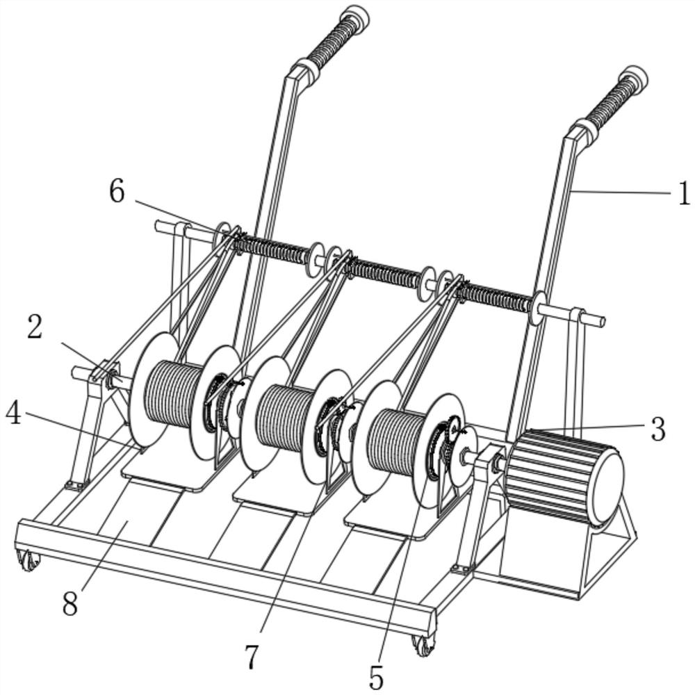
[0003] Currently, during the laying process of the optical cable, the reeled optical cable is wound up at the position of the reel, and the reel is placed on the road of laying the optical cable at the same time, because the cables that need to be installed during the laying process are different, they need to be installed on the main shaft of the reel. Installing multiple optical cable fairies requires different lengths for different optical cables, so that the retracting and unwinding speeds of multiple different optical cable clusters are different, and the cables with slow winding speeds will retract and unwind the cables with fast winding speeds on the line. Interference caused by accumulation and winding, and at the same time, because the cable is wound around the outside of the drum during the winding and unwinding process, when retracting and unwinding from one side of the drum to the other, the cable with a fast rewinding and unwinding speed will drive the slow rewinding and unwinding cable. The cable moves quickly outside the drum, which causes the wear and tear of the slow-winding cable to increase. For this reason, we propose a low-stress optical cable take-up and take-off device

Method used


Image

  • Low-stress optical fiber cable take-up and pay-off device
  • Low-stress optical fiber cable take-up and pay-off device
  • Low-stress optical fiber cable take-up and pay-off device

Examples


Embodiment Construction

[0026] The following will clearly and completely describe the technical solutions in the embodiments of the present invention with reference to the accompanying drawings in the embodiments of the present invention. Obviously, the described embodiments are only some, not all, embodiments of the present invention. Based on the embodiments of the present invention, all other embodiments obtained by persons of ordinary skill in the art without making creative efforts belong to the protection scope of the present invention.

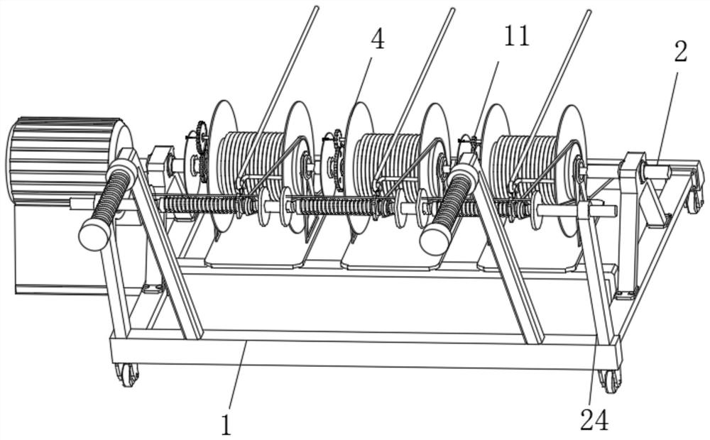
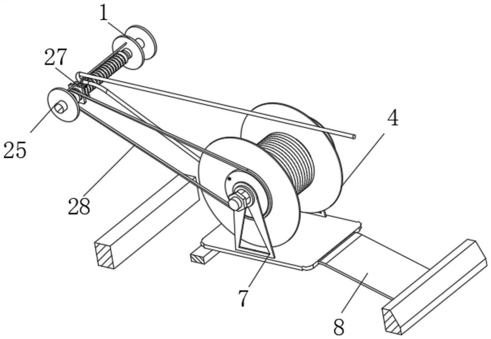
[0027] see Figure 1-10 , the present invention provides a technical solution: a low-stress optical cable retracting and unwinding device. In this solution, when the existing optical cable is retracted and unwound, the required optical cable time is different when different optical cables are retracted, causing the optical cable to drag. The speed of movement does not change, dragging the slow cable interferes with the fast cable, and causes wear and tear on t...


PUM


Abstract

The invention discloses a low-stress optical fiber cable take-up and pay-off device. The low-stress optical fiber cable take-up and pay-off device comprises a trailer body, a plurality of take-up andpay-off cylinders, speed regulating assemblies and cable moving assemblies, wherein the trailer body is connected with a rolling main shaft; the plurality of take-up and pay-off cylinders are used fortaking up and paying off different optical fiber cables and penetrate through the outer side of the rolling main shaft; each speed regulating assembly is connected to one side of the corresponding take-up and pay-off cylinder and used for regulating the take-up and pay-off speed of the take-up and pay-off cylinder; and each cable moving assembly is connected to the other side of the correspondingtake-up and pay-off cylinder and used for synchronously moving the taken-up and paid-off optical fiber cables at the take-up speed of the take-up and pay-off cylinders. Each speed regulating assemblyis installed on one side of the corresponding take-up and pay-off cylinder, so that the optical fiber cables at the take-up and pay-off cylinders can be conveniently taken up at different rotating speeds; selective movements of the take-up and pay-off cylinders are achieved at transmission pieces, so that take-up and pay-off speeds can be conveniently selected for the different optical fiber cables, and the influence of the optical fiber cables with the low take-up and pay-off speed on the optical fiber cables with the high take-up and pay-off speed is reduced; and meanwhile, through the arranged cable moving assembly, the abrasion influence on the optical fiber cables can be reduced conveniently in the optical fiber cable dragging process.

Description

technical field [0001] The invention relates to the technical field of optical cables, in particular to a low-stress optical cable take-up and release device. Background technique [0002] Optical fiber cable is manufactured to meet optical, mechanical or environmental performance specifications. It is a communication communication that uses one or more optical fibers placed in a sheath as a transmission medium and can be used individually or in groups. cable assembly. Optical cables are mainly composed of optical fibers (glass filaments as thin as hair), plastic protective sleeves and plastic sheaths. There are no metals such as gold, silver, copper, and aluminum in optical cables, and generally have no recycling value; optical cables are composed of a certain number of optical fibers in a certain way. The cable core is covered with a sheath, and some are also covered with an outer sheath, which is used to realize a communication line for optical signal transmission; most ...

Claims


Application Information

Patent Timeline
IPC IPC(8): B65H75/42B65H75/44
CPCB65H75/425B65H75/4481B65H75/4486B65H2701/32
Inventor 谢绍良
Owner 广州大鹏机械设计有限公司
Learn More