
Door speed limiter

A speed limiter and roller technology, which is applied to door/window accessories, switches with braking devices, wing leaf parts, etc., can solve the problems that the speed restriction of the door body cannot be realized, and achieve a large adjustable range of binding force, The effect of improving safety

Inactive Publication Date: 2021-02-23
丁井池
View PDF0 Cites 0 Cited by
  • Summary
  • Abstract
  • Description
  • Claims
  • Application Information

AI Technical Summary

Problems solved by technology

[0003] The purpose of the present invention is to provide a door speed limiter to solve the problem that the existing door body fixer cannot realize the speed constraint of the whole process of door body movement

Method used


Image

  • Door speed limiter
  • Door speed limiter
  • Door speed limiter

Examples


Embodiment 1

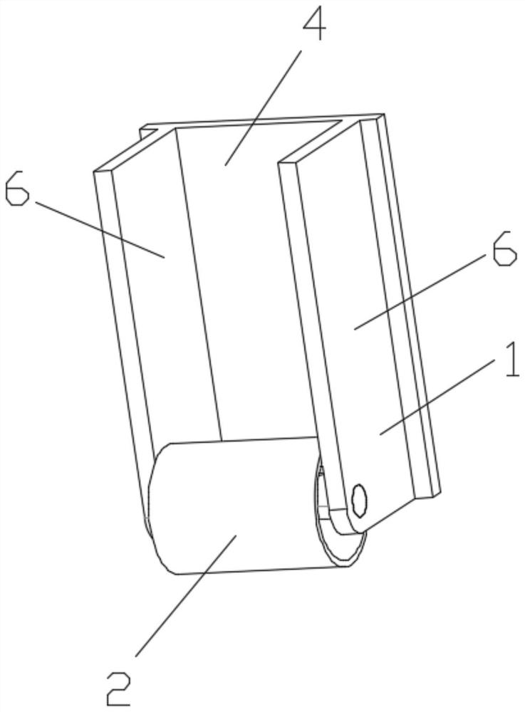
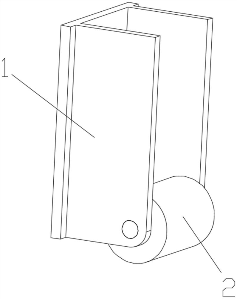
[0025] A door speed governor, the speed governor includes a base 1, a roller 2 and a centrifugal rolling rod 3;

[0026] The main body of the base 1 is a frame structure, the frame structure is composed of three rectangular plates, the rectangular plate 4 in the middle is fixedly connected with the movable door panel, the rectangular plates 6 on both sides are symmetrically arranged, and the rectangular plates 6 on both sides are symmetrical Roller rotating holes 7 are all provided; one of the rectangular plates on both sides of the rectangular plates 6 is provided with a wave plate 8 inside, and the wave plate 8 is an arc plate with the central axis of the wheel rotating holes 7 as the central axis, and the bottom of the arc plate The raised blocks 9 are evenly distributed on the surface;

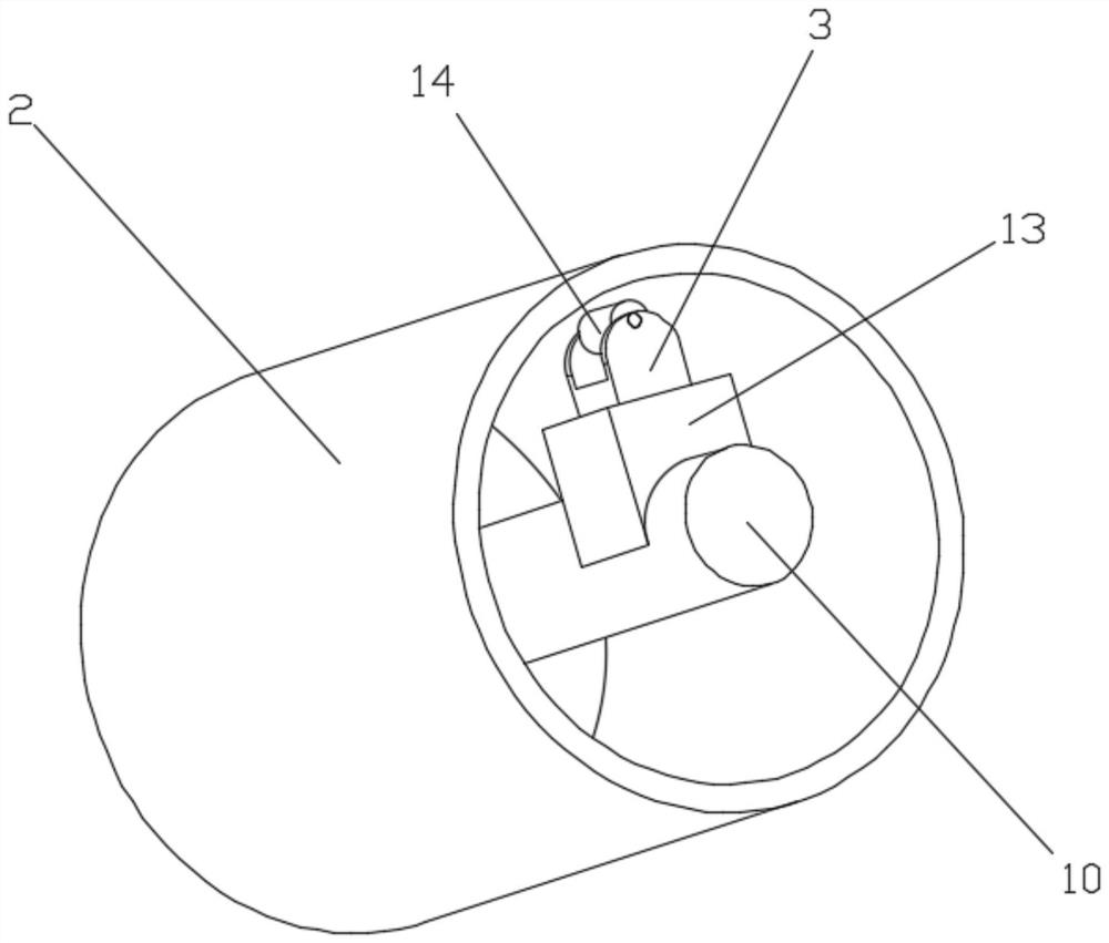
[0027] see Figure 4 The main body of the roller 2 is an open ring shell with a shaft 10 in the center. The shaft 10 at the center of the roller 2 matches the wheel rotation hole 7 on the...


PUM


Abstract

The invention discloses a door speed limiter. The door speed limiter comprises a base, a roller and a centrifugal rolling rod, the base body is of a frame structure, the frame structure is composed ofthree rectangular plates, a fluctuation plate is arranged on the inner side of one of the rectangular plates on the two sides, the fluctuation plate is an arc plate with the central axis of a rollerrotating hole as the central axis, and protruding blocks are evenly distributed on the lower surface of the arc plate. a roller body is a circular ring shell with a shaft in the center and an openingin one side, the shaft in the center of the roller is matched with the roller rotating hole in the base, and a centrifugal rolling rod sliding groove is formed in the shaft on the opening side of thecircular ring shell and used for being matched with a centrifugal rolling rod outer shell; and the centrifugal rolling rod body is a rectangular block, and a rotating wheel is arranged at one end of the rectangular block and can rotate around a rotating wheel restraining hole in the rectangular block. The problem that an existing door body fixator cannot restrain the speed of the whole movement process of a door body is solved.

Description

technical field [0001] The invention relates to a door panel movement speed limiter, in particular to a door speed limiter. Background technique [0002] At present, with the improvement of living standards, people's requirements for the quality of life are increasing day by day, and they begin to pay attention to the details of life. In daily life, it is found that in places with abundant wind resources, the door is often opened suddenly or Closing, making a sudden sound or even hurting people, most of the restrictions on the door are currently adding a magnetic retainer behind the door panel to keep the door open. Once the magnetic retainer is separated, the door will be restored. The out-of-control state cannot play a role in restricting the whole process of door panel activity. Contents of the invention [0003] The purpose of the present invention is to provide a door speed limiter, which is used to solve the problem that the existing door body fixer cannot realize t...

Claims


Application Information

Patent Timeline
IPC IPC(8): E05F5/06
CPCE05F5/06E05Y2900/132
Inventor 丁井池
Owner 丁井池
Learn More