One-stop multifunctional assembly test line

A multi-functional, test-line technology, applied in the direction of measuring devices, mechanical valve testing, fluid tightness testing, etc., can solve the problems of lack of continuity, low resource utilization, labor and time, etc., to achieve strong consistency, Improved product quality and multifunctional effects

Inactive Publication Date: 2020-11-20
李思
View PDF10 Cites 0 Cited by
  • Summary
  • Abstract
  • Description
  • Claims
  • Application Information

AI Technical Summary

Problems solved by technology

Furthermore, manual sorting of components will require a lot of labor and time. The traditional assembly and testing line lacks effective continuity between the processes, and the detection and test methods between the processes are backward, and the test data is difficult to guarantee. Resources The utilization rate is low, therefore, it is necessary to improve the traditional assembly test line to provide a one-stop multi-functional coordinated operation assembly test line

Method used


Image

  • One-stop multifunctional assembly test line
  • One-stop multifunctional assembly test line
  • One-stop multifunctional assembly test line

Examples


Embodiment 1

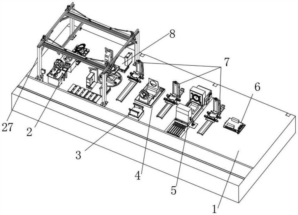
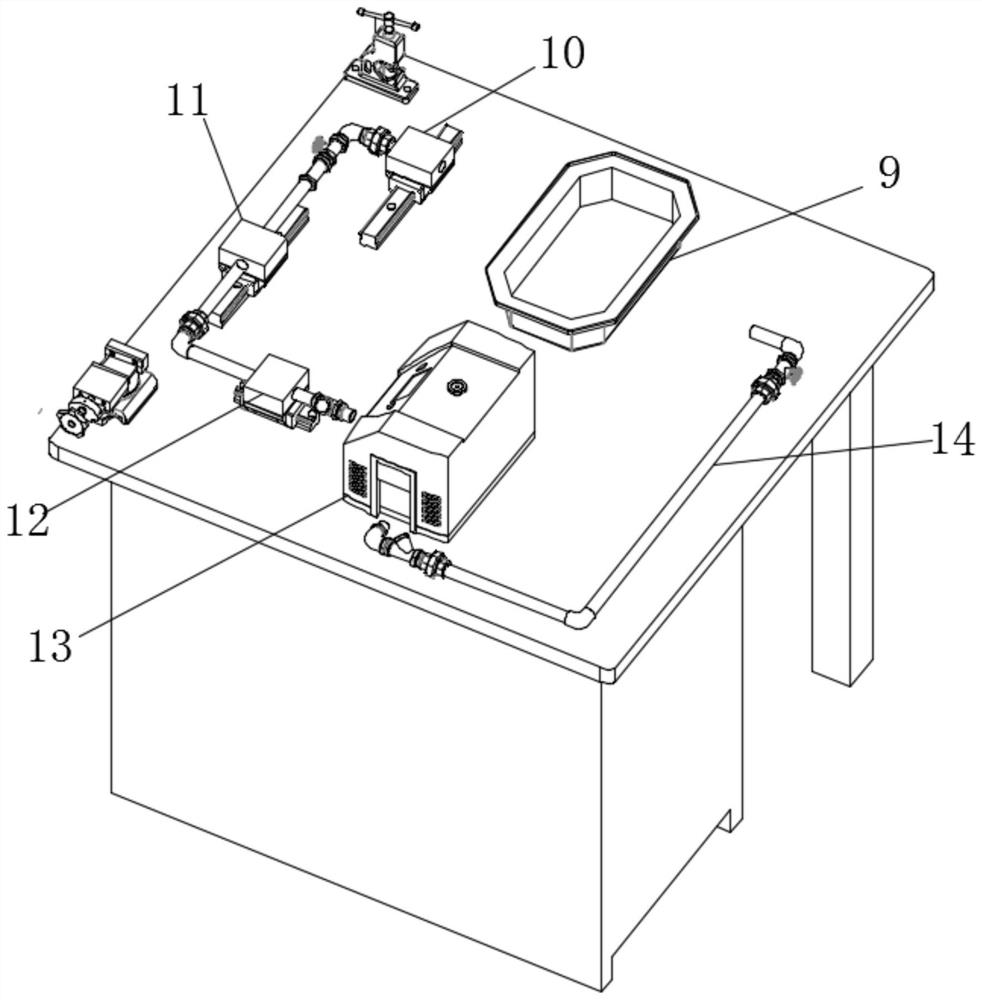
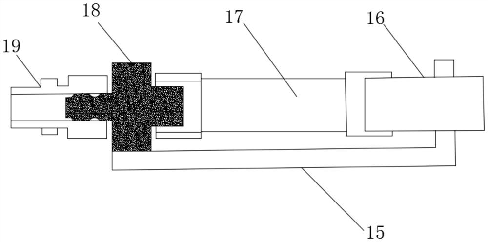
[0021] Such as Figure 1-5 As shown, the present invention provides a technical solution: a one-stop multifunctional assembly test line, including a working table 1, a cargo handling area 27 is fixedly installed on the top side of the working table 1, and a valve component pre-assembly is arranged inside the cargo handling area 27 Area 2 and valve body assembly area 8, the top of the worktable 1 is equidistantly provided with the conveying robot arm 7, and the valve plate test area 4 and the valve body test area 5 are fixedly installed between the adjacent conveying robot arms 7, and the valve plate test area 4 There is a valve body rework area 3 on one side, a trolley system 6 is fixedly installed on the top of the other side of the workbench 1, a controller is fixedly installed on the side of the workbench 1, and the valve component pre-assembly area 2 includes a part placement box 9 and an airtight Detector 13, the air-tightness detector 13 is provided with an air inlet sid...

Embodiment 2

[0023] As shown in Figure: 4-5, valve body test area 5 comprises test cell body 20, and test cell body 20 interior is provided with water recovery tank 23 and water filter tank 25, is provided with between water recovery tank 23 and water filter tank 25 The laminar flow filter wall 24, the top of the test tank 20 is provided with a movable metal mesh 22, the top of the movable metal mesh 22 is fixedly installed with a centrifugal pump 21, the inside of the water filter pool 25 is provided with a filter 26, and the cargo handling area 27 is provided with a lift The control system and sliding control system, the lifting system and the sliding control system are electrically connected to the controller respectively, and the cart system 6 includes a drive unit, a control chip unit, an obstacle avoidance sensor, an alarm device, a power switch, a controller and an operation panel, and a valve Body test area 5 also includes water inlet filter, check valve, stop valve, multi-stage cen...


PUM


Abstract

The invention discloses a one-stop multifunctional assembly test line, and relates to the technical field of assembly test lines. The one-stop multifunctional assembly test line comprises a workbenchtop, a goods carrying area is fixedly mounted on one side of the top of the workbench top, and a valve part pre-assembling area and a valve body assembling area are arranged in the goods carrying area. Conveying mechanical arms are arranged at the top of the workbench top at equal intervals. A valve plate test area and a valve body test area are fixedly installed between every two adjacent conveying mechanical arms, and a valve body repair area is arranged on one side of each valve plate test area. A cart system is fixedly installed at the top of the other side of the workbench top, and a controller is fixedly installed on the side face of the workbench top. The strength test, the sealing test, the control pipe system leakage-free test and the action test of listed products are automatically carried out, various test data required by the tests can be automatically detected, and all the detected data can be automatically stored and remotely transmitted.

Description

technical field [0001] The invention relates to the technical field of assembly test lines, in particular to a one-stop multifunctional assembly test line. Background technique [0002] In conventional assembling devices such as electric motors and motor drive devices, the selection itself of a plurality of components is manually performed. There are errors in the characteristics of the plurality of components, and the characteristics of the product are determined based on the errors of the plurality of components. Therefore, if components are randomly selected and assembled, there is a problem that the characteristics of the finished product become the characteristics of each component. Furthermore, manual sorting of components will require a lot of labor and time. The traditional assembly and testing line lacks effective continuity between the processes, and the detection and test methods between the processes are backward, and the test data is difficult to guarantee. Res...

Claims


Application Information

Patent Timeline
Patent Type & Authority Applications(China)
IPC IPC(8): G01M13/003G01M3/00
CPCG01M3/00G01M13/003
Inventor 李思
Owner 李思
Why Eureka
Try Eureka