
Reinforced sintering equipment, charge level cooling device and control method of charge level cooling device

The technology of a cooling device and a control method, which is applied in the field of sintering, can solve the problems of rising defective rate of sintered ore, inability to realize enhanced sintering, easy burnout of gas injection device pipe row facilities, etc.

Active Publication Date: 2021-02-23
ZHONGYE-CHANGTIAN INT ENG CO LTD
View PDF5 Cites 0 Cited by
  • Summary
  • Abstract
  • Description
  • Claims
  • Application Information

AI Technical Summary

Problems solved by technology

[0005] But this technology also has the following problems: 1) if the starting point of gas injection is set too far ahead, that is, too close to the ignition position, the red hot material surface just out of the ignition furnace is easy to directly ignite the ejected gas, so , not only does the injected gas fail to strengthen the sintering effect, but it is also easy to burn out the pipe and row facilities in the gas injection device; 2) If the starting point of the gas injection is set too far back, although the ignition phenomenon can be effectively suppressed, the Since sintering is a ventilation operation, there is self-heat storage phenomenon in the production process, and the upper material layer is the area most in need of supplementary heat. If the gas is injected too late, the combustion zone has moved down to the middle and lower parts of the material layer. The material layer cannot be supplemented by gas, and the purpose of strengthening sintering cannot be achieved, and there may even be a phenomenon that the rate of defective sintered ore increases due to excessive heat in the middle and lower parts

Method used


Image

  • Reinforced sintering equipment, charge level cooling device and control method of charge level cooling device
  • Reinforced sintering equipment, charge level cooling device and control method of charge level cooling device
  • Reinforced sintering equipment, charge level cooling device and control method of charge level cooling device

Examples


Embodiment 1

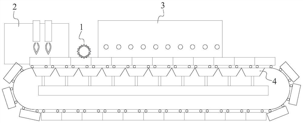
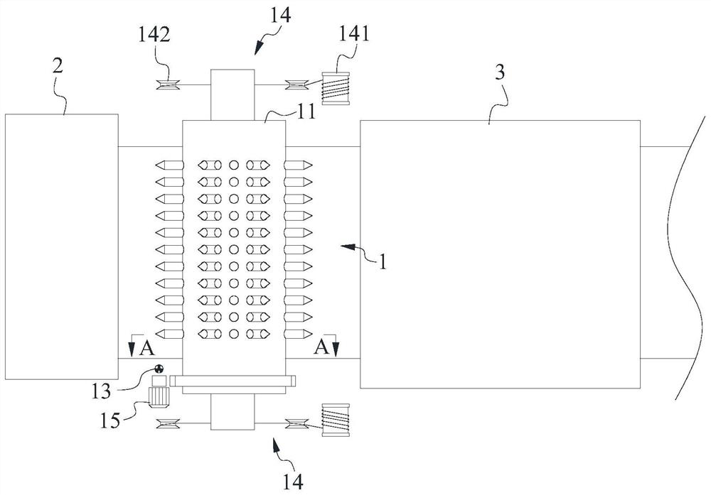
[0040] like Figure 1-4 As shown, the present invention provides a material surface cooling device. The material surface cooling device 1 is arranged next to the ignition device 2 in the sintering equipment, and is located downstream of the ignition device 2 and above the sintering material layer. In detail, the material surface cooling device 1 includes a rotating drum 11, which can be driven to rotate by a driving component. Specifically, the driving component can be a driving motor 15, which can be directly connected to the rotating drum 11, or can be provided with a variable speed. Mechanism; the cylinder wall of the drum 11 is provided with a number of rods 111. During the rotation of the drum 11, at least some of the rods 111 can be at least partially inserted into the sintered material layer, and the drum 11 is also filled with cooling fluid, and at least some of the rods The body 111 is hollow, so as to form an injection channel 111a inside; each hollow rod body 111 ca...

Embodiment 2

[0067] The present invention also provides an intensified sintering device, comprising a gas injection device 3 and a material surface cooling device 1, the gas injection device 3 is arranged next to the material surface cooling device 1, and is located downstream of the material surface cooling device 1, wherein the material The surface cooling device 1 is the material surface cooling device 1 involved in the first embodiment above.

[0068] Since the above-mentioned material level cooling device 1 already has the above technical effects, then the intensified sintering equipment having the material level cooling device 1 should also have similar technical effects.

Embodiment 3

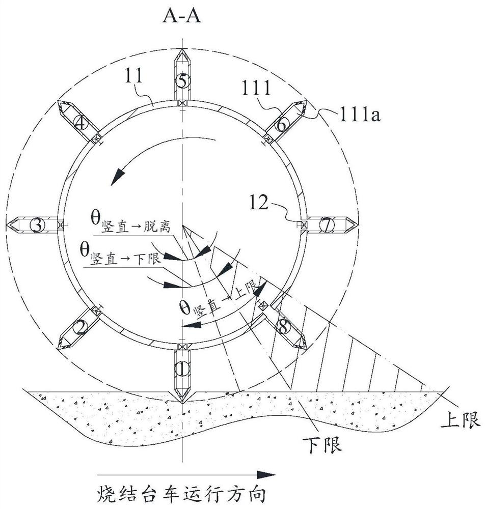
[0070] like Figure 5 , Image 6 As shown, the present invention also provides a control method for a material surface cooling device, which is suitable for the material surface cooling device involved in Embodiment 1, including:

[0071] Step S1, obtaining the rotation angle α of the drum at different times;

[0072] Step S2, compare θ 竖直→下限 , θ 竖直→上限 , θ 竖直→i,0 、α t Whether it satisfies θ 竖直→下限 ≤((θ 竖直→i,0 +α t %2π)%2π)≤θ 竖直→上限 condition, if yes, perform the following step S3, if not, perform the following step S4;

[0073] Step S3, controlling the on-off valve of the hollow rod body numbered i to be in an open state;

[0074] Step S4, controlling the on-off valve of the hollow rod body numbered i to be in a closed state;

[0075] Among them, α t is the rotation angle of the drum at time t, θ 竖直→下限 , θ 竖直→上限 are the angles between the vertical position and the lower limit and upper limit of the injection station in the direction of rotation, θ 竖直→i,0 is the an...


PUM


Abstract

The invention discloses reinforced sintering equipment, a charge level cooling device and a control method of the charge level cooling device. The charge level cooling device is arranged close to an ignition device in the sintering equipment, located on the downstream of the ignition device and above a sintering material layer and comprises a rotary drum, wherein a plurality of rod bodies are arranged on the drum wall of the rotary drum, in the rotating process of the rotary drum, at least a part of the rod bodies can be at least partially inserted into the sintering material layer, the rotarydrum is further filled with cooling fluid, and at least a part of the rod bodies are hollow; and the charge level cooling device further comprises a controller, a rotation angle sensor and switch valves arranged in the hollow rod bodies, the controller is in signal connection with the rotation angle sensor and the switch valves, the rotation angle sensor is used for monitoring the rotation angleof the rotary drum, the controller can control the switch valve with the number of i in the rod body to be in an open state, wherein the switch valve meets the first condition that ((theta<vertical toi,0>+alpha<t>% 2pi)%2pi) is larger than or equal to theta<vertical to lower limit and smaller than or equal to theta<vertical to upper limit>,and the switch valve in the rod body with the number i which does not meet the first condition can be controlled to be in a closed state.

Description

technical field [0001] The invention relates to the technical field of sintering, in particular to an intensified sintering device, a material surface cooling device and a control method thereof. Background technique [0002] The sintering process is a key link in the ironmaking process. Its principle is to mix various powdery iron-containing raw materials with an appropriate amount of fuel and flux, and add an appropriate amount of water. After mixing and pelletizing, the materials are made on the sintering equipment. A series of physical and chemical changes occur and sintered into blocks to form the main raw material sinter in the current blast furnace ironmaking process. [0003] However, the pollution and energy consumption of the sintering process are relatively high, and its energy consumption ranks second in the iron and steel industry, and its pollution load accounts for 40% of the iron and steel industry, ranking first. With increasingly stringent environmental pro...

Claims


Application Information

Patent Timeline
IPC IPC(8): F27D9/00F27D19/00F27B21/00F27B21/08F27B21/14
CPCF27D9/00F27D19/00F27B21/00F27D2009/0083F27D2009/007F27D2019/0056
Inventor 刘前叶恒棣周浩宇王业峰
Owner ZHONGYE-CHANGTIAN INT ENG CO LTD
Learn More