
Buffer circuit, integrated circuit and electronic equipment

A buffer, circuit technology, applied in logic circuits, eliminating voltage/current interference, electrical components, etc., can solve problems such as poor EMI performance

Pending Publication Date: 2021-02-23
VIVO MOBILE COMM CO LTD
View PDF2 Cites 1 Cited by
  • Summary
  • Abstract
  • Description
  • Claims
  • Application Information

AI Technical Summary

Problems solved by technology

[0005] The purpose of the embodiment of the present application is to provide a buffer circuit, integrated circuit and electronic equipment, which can solve the problem of relatively poor EMI performance in the buffer circuit in the prior art

Method used


Image

  • Buffer circuit, integrated circuit and electronic equipment
  • Buffer circuit, integrated circuit and electronic equipment
  • Buffer circuit, integrated circuit and electronic equipment

Examples


Embodiment Construction

[0021] The following will clearly and completely describe the technical solutions in the embodiments of the present application with reference to the drawings in the embodiments of the present application. Obviously, the described embodiments are part of the embodiments of the present application, not all of them. Based on the embodiments in this application, all other embodiments obtained by persons of ordinary skill in the art without creative efforts fall within the protection scope of this application.

[0022] The terms "first", "second" and the like in the specification and claims of the present application are used to distinguish similar objects, and are not used to describe a specific sequence or sequence. It should be understood that the terms so used are interchangeable under appropriate circumstances such that the embodiments of the application can be practiced in sequences other than those illustrated or described herein, and that references to "first," "second," et...


PUM


Abstract

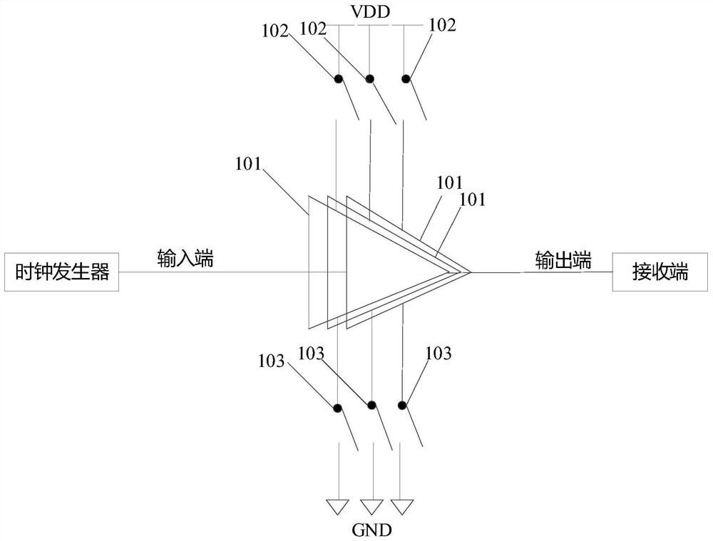
The invention discloses a buffer circuit, an integrated circuit and electronic equipment, the buffer circuit comprises M driving units, M first switches and M second switches, and M is a positive integer greater than 1; the first ends of the M driving units are respectively connected with a power supply through the M first switches and are respectively grounded through the M second switches, the second ends of the M driving units are connected with one another to be used as the input end of the buffer circuit, and the third ends of the M driving units are connected with one another to be usedas the output end of the buffer circuit; and the M first switches and the M second switches are used for controlling the working modes of the M driving units, and the M driving units are used for amplifying signals received by the input end of the buffer circuit so as to output driving signals with the driving capacity corresponding to the working modes at the output end of the buffer circuit, andthe working mode is used for representing the driving capability of the M driving units. According to the embodiment of the invention, the EMI performance of the buffer circuit can be optimized.

Description

technical field [0001] The application belongs to the technical field of communication, and in particular relates to a buffer circuit, an integrated circuit and electronic equipment. Background technique [0002] Currently, a clock module of a display driver integrated circuit (IC) usually adds a buffer circuit for output waveform shaping, and the output signal of the buffer circuit is used as a reference clock for a back-end frequency division or timing module. [0003] In order to ensure that there is no functional risk, a traditional buffer circuit is usually provided with a certain driving capability. However, an inappropriate setting of the driving capability will often generate strong electromagnetic interference (Electromagnetic Interference, EMI). These EMI interferences will radiate and couple to the antennas that are close to it, and the driver IC is usually coupled in parallel with the antennas, resulting in a relatively high efficiency of EMI interference radiati...

Claims


Application Information

Patent Timeline
Patent Type & Authority Applications(China)
IPC IPC(8): H03K19/003
CPCH03K19/00315H03K19/00338H03K19/00361
Inventor 刘广辉
Owner VIVO MOBILE COMM CO LTD
Learn More