Large-scale cluster calling link configuration optimization method based on complex network
A configuration optimization and complex network technology, applied in the direction of data exchange network, digital transmission system, electrical components, etc., can solve the problem that the best ability of physical path call cannot be fully utilized, and achieve the effect of reducing time consumption
- Summary
- Abstract
- Description
- Claims
- Application Information
AI Technical Summary
Problems solved by technology
Method used
Image

Examples
Embodiment 1
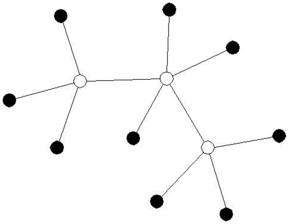
[0030] Such as Figure 1-7 , the present invention provides a large-scale cluster call link configuration optimization method based on a complex network, and establishes solid nodes and hollow nodes, wherein the hollow nodes are Tor switches on different racks, the solid nodes are application servers, and the difference between the hollow nodes and the solid nodes The association between hollow nodes and hollow nodes is a physical path (such as figure 1 shown); specifically, the following steps are also included:
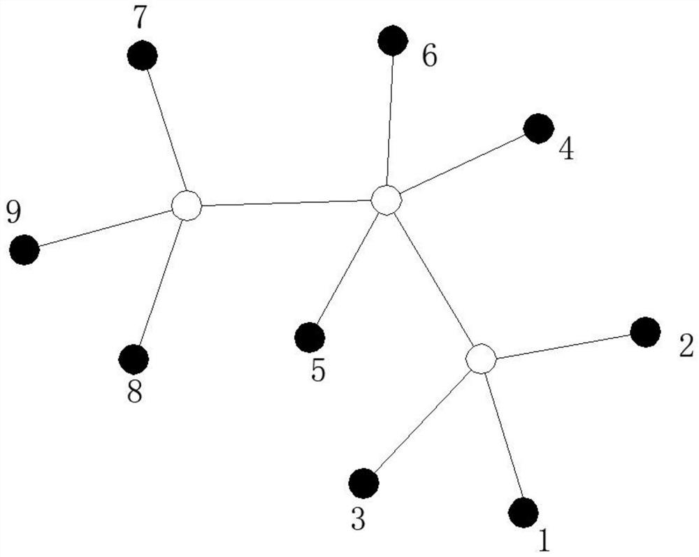
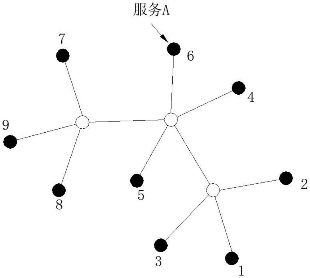
[0031] 1. Number the solid nodes used as application servers, and the numbering sequence is from 1 to 9 (such as figure 2 shown); configure the service to one of the solid nodes in the cluster as an application server through the cloud computing platform (such as image 3 As shown, service A is configured to server No. 6 in the cluster through the cloud computing platform). During the service configuration process, the specific process includes information colle...
PUM
 Abstract
Description
Claims
Application Information
 - Generate Ideas
- Intellectual Property
- Life Sciences
- Materials
- Tech Scout
- Unparalleled Data Quality
- Higher Quality Content
- 60% Fewer Hallucinations
Browse by: Latest US Patents, China's latest patents, Technical Efficacy Thesaurus, Application Domain, Technology Topic, Popular Technical Reports.
© 2025 PatSnap. All rights reserved.Legal|Privacy policy|Modern Slavery Act Transparency Statement|Sitemap|About US| Contact US: help@patsnap.com