A split-flow flue gas desulfurization and denitrification treatment system and method

A technology for desulfurization, denitrification, and treatment systems, applied in the direction of separation methods, gas treatment, chemical instruments and methods, etc., can solve the problems of polluting air, consuming more fuel, etc., achieve low input costs, provide production efficiency, and have obvious effects

Active Publication Date: 2022-05-03
ZHONGYE-CHANGTIAN INT ENG CO LTD
View PDF10 Cites 0 Cited by
  • Summary
  • Abstract
  • Description
  • Claims
  • Application Information

AI Technical Summary

Problems solved by technology

The hot blast stove itself produces a certain amount of flue gas. Since the hot blast stove is burning, the flue gas produced contains pollutants such as nitrogen dioxide and nitrogen monoxide; in the prior art, the gas generated by the hot blast stove is directly discharged, polluting the air
At the same time, the hot blast stove uses air at normal temperature as the combustion-supporting gas, and heating this part of the combustion-supporting gas to the temperature required by the heat exchange medium (generally 400-460°C) requires a large amount of fuel; that is to say, part of the fuel in the hot blast stove needs to be used It is used to heat the combustion-supporting gas, resulting in the need to consume more fuel and produce a larger amount of pollutant-containing flue gas

Method used


Image

  • A split-flow flue gas desulfurization and denitrification treatment system and method
  • A split-flow flue gas desulfurization and denitrification treatment system and method

Examples


Embodiment 1

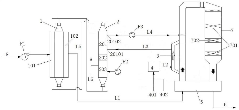
[0110] Such as figure 1 As shown, a split-flow flue gas desulfurization and denitrification treatment system includes an activated carbon adsorption tower 1, an activated carbon desorption tower 2, a hot blast stove 4, an air mixing chamber 3 and an SCR reactor 7. According to the direction of flue gas, one side of the activated carbon adsorption tower 1 is provided with a raw flue gas inlet 101 , and the other side is provided with a desulfurized flue gas outlet 102 . The desulfurized flue gas outlet 102 is connected to the air inlet of the SCR reactor 7 through the first pipeline L1. The clean flue gas discharged from the SCR reactor 7 is discharged from the exhaust port of the SCR reactor 7 . A bypass pipe is drawn from the first pipeline L1 to form the air mixing chamber 3, the air inlet of the air mixing chamber 3 is connected to the upstream position of the first pipeline L1, and the exhaust port of the air mixing chamber 3 is connected to at the downstream position of...

Embodiment 2

[0113] Example 1 was repeated except that the system also included a GGH heat exchanger 5 . The gas outlet of the SCR reactor 7 is connected with the exhaust pipe 6 . The GGH heat exchanger 5 is connected to the first pipe L1 and the exhaust pipe 6 respectively. The flue gas desulfurized by the activated carbon adsorption tower 1 is sent to the air inlet of the SCR reactor 7 after heat exchange by the GGH heat exchanger 5 . The clean flue gas discharged from the SCR reactor 7 is discharged through the exhaust pipe 6 after being heat-exchanged by the GGH heat exchanger 5 . The position where the air inlet of the air mixing chamber 3 leads from the first pipeline L1 is located downstream of the connection position between the GGH heat exchanger 5 and the first pipeline L1.

Embodiment 3

[0115] Repeat embodiment 2, according to the trend of activated carbon, the activated carbon outlet of described activated carbon desorption tower 2 is connected with the activated carbon inlet of activated carbon adsorption tower 1 by the first activated carbon conveying device L6. The activated carbon outlet of the activated carbon adsorption tower 1 is connected with the activated carbon inlet of the activated carbon desorption tower 2 through the second activated carbon delivery device L5.


PUM

PropertyMeasurementUnit
heightaaaaaaaaaa
heightaaaaaaaaaa

Abstract

The invention discloses a split-flow flue gas desulfurization and denitrification treatment system and method. The split-flow flue gas desulfurization and denitrification treatment system includes an activated carbon adsorption tower, an activated carbon analysis tower, an air mixing chamber, a hot blast furnace and an SCR reactor; The air mixing chamber mixes the hot air generated by the fuel combustion of the hot blast furnace and the part of the desulfurized flue gas after the desulfurization treatment of the activated carbon adsorption tower to form a heat medium, which is used to realize the thermal regeneration and heating of the activated carbon in the heating section of the activated carbon desorption tower The SCR system requires denitrification flue gas. The system and method of the invention have low input cost, simple structure, strong adaptability and practicability, high control precision, and obvious flue gas desulfurization and denitrification effects.

Description

technical field [0001] The invention relates to flue gas desulfurization and denitrification technology, in particular to a split-flow flue gas desulfurization and denitrification treatment system and method, belonging to the technical field of flue gas purification. Background technique [0002] For industrial flue gas, especially for sintering machine flue gas in the iron and steel industry, flue gas desulfurization and denitrification technology is a flue gas purification technology applied to the chemical industry where multiple nitrogen oxides and sulfur oxides are generated. Nitrogen oxides and sulfur oxides are one of the main sources of air pollution. Most of flue gas simultaneous desulfurization and denitrification technologies are currently in the research and industrial demonstration stage, but because it can simultaneously achieve desulfurization and denitrification in one system, especially with the X Control standards are becoming increasingly stringent, and d...

Claims


Application Information

Patent Timeline
Patent Type & Authority Patents(China)
IPC IPC(8): B01D53/02B01D53/04B01D53/86B01D53/75B01D53/56B01D53/62
CPCB01D53/02B01D53/0454B01D53/0446B01D53/86B01D53/8631B01D53/864B01D53/75B01D2253/102B01D2259/4009B01D2258/0283
Inventor 刘昌齐魏进超叶恒棣康建刚
Owner ZHONGYE-CHANGTIAN INT ENG CO LTD
Why Eureka
Try Eureka