
Process method for manufacturing rotor shielding sleeve by mechanical processing

A technology of mechanical processing and process method, applied in the direction of manufacturing tools, metal processing, metal processing equipment, etc., can solve problems such as affecting the overall operation of the motor, large performance deviation, and difficult to control the welding quality of the rotor shielding sleeve.

Active Publication Date: 2022-01-07
HARBIN ELECTRIC POWER EQUIP
View PDF14 Cites 0 Cited by
  • Summary
  • Abstract
  • Description
  • Claims
  • Application Information

AI Technical Summary

Problems solved by technology

The thickness and size of the rotor shielding sleeve manufactured by the spinning process are uneven, and the straightness is poor. After being assembled on the rotor, there will be overall runout difference, which will affect the subsequent dynamic balance of the rotor and even affect the overall operation of the motor, reducing the service life; the sheet metal welding and rolling process manufacturing The welding quality of the rotor shield sleeve is difficult to control, and the performance deviation of the weld seam and the heat-affected zone is relatively large. After being assembled to the rotor, it is easy to have defects such as bulges and wrinkles under pressure, which will affect the operation of the motor and even cause accidents; in order to ensure that the shielded motor The performance and stability of the rotor shielding sleeve requires a new rotor shielding sleeve manufacturing process

Method used


Image

  • Process method for manufacturing rotor shielding sleeve by mechanical processing
  • Process method for manufacturing rotor shielding sleeve by mechanical processing

Examples


Embodiment Construction

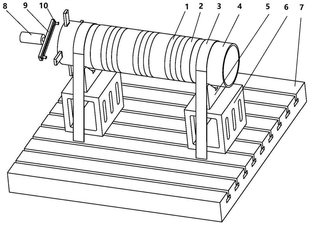
[0018] Such as figure 1 As shown, a process method for manufacturing a rotor shielding sleeve by mechanical processing includes the following steps:

[0019] 1) Clean the workbench 7 of the boring machine to ensure the cleanliness of the workbench;

[0020] 2) Install the square box 6 on the workbench 7 respectively, install the V-shaped iron 5 on the square box, and adjust the level of the V-shaped iron 5 with a spirit level, and the parallelism of the V-shaped iron 5 relative to the workbench 7 is not greater than 0.02mm;

[0021] 3) Install the rotor shielding sleeve 4 horizontally on the V-shaped iron 5. The outer surface of the rotor shielding sleeve 4 is wrapped with a 3mm thick oil-resistant rubber plate 2 for reducing vibration during processing. The tape 1 fixes the rotor shielding sleeve 4 and the oil-resistant rubber plate 2. The two ends of the rotor shielding sleeve 4 are wound with shrinkage tape 3 at a position 200 mm away from the end face, and the shrinkage t...


PUM


Abstract

The invention relates to a process method for manufacturing rotor shielding sleeves by mechanical processing; a square box (6) is installed on a workbench (7), a V-shaped iron (5) is installed on the square box (6), and the V-shaped iron ( 5) Horizontal to within 0.02mm; the rotor shielding sleeve (4) is installed on the V-shaped iron (5), and a 3mm thick oil-resistant rubber plate (2) is wound around the outer circle of the rotor shielding sleeve (4), and the oil-resistant rubber plate (2) is wrapped with tape (1) The rubber plate (2) is fixed, and the rotor shielding sleeve (4) is fixed on the workbench (7) with the shrink band (3); the inner hole of the rotor shielding sleeve is roughly and finely machined with a bridge type boring tool (10) on the boring machine, The boring parameters are cutting depth 0.05mm, feed rate 0.1mm, speed 80-100r / min; leave 0.05mm margin for the final size of the inner hole of the rotor shielding sleeve, assemble the self-made rolling cutter (8) on the main shaft of the boring machine, roll The inner hole of the rotor shielding sleeve (4) improves the smoothness. The invention can realize one-time clamping of the rotor shielding sleeve on the boring machine, complete the processing of the inner hole of the rotor shielding sleeve, and ensure the size tolerance, shape tolerance and smoothness of the inner hole.

Description

Technical field: [0001] The invention relates to a process method for manufacturing a rotor shielding sleeve by mechanical processing. Background technique: [0002] The rotor shielding sleeves used in shielded motors are mainly manufactured in two ways: spinning process and plate welding and rolling process. The thickness and size of the rotor shielding sleeve manufactured by the spinning process are not uniform, and the straightness is poor. After being assembled on the rotor, there will be overall runout difference, which will affect the subsequent dynamic balance of the rotor and even affect the overall operation of the motor, reducing the service life; the plate welding and rolling process manufacturing The welding quality of the rotor shielding sleeve is difficult to control, and the performance deviation of the weld seam and the heat-affected zone is relatively large. After being assembled to the rotor, defects such as bulges and wrinkles are prone to occur under pres...

Claims


Application Information

Patent Timeline
Patent Type & Authority Patents(China)
IPC IPC(8): B23B35/00B23B41/00B23P9/02B23Q3/08B23Q37/00H02K15/00H02K15/14
CPCH02K15/00H02K15/14B23B41/00B23B35/00B23Q37/00B23Q3/08B23Q3/084B23P9/02
Inventor 张涛黄秀波唐浩宇于志佳郑维赵环宇宋亮刘宇晨柴文虎刘继东杨振
Owner HARBIN ELECTRIC POWER EQUIP
Learn More