Automatic welding device for vehicle thermal forming floor cross beam

An automatic welding and thermoforming technology, applied in auxiliary devices, welding equipment, welding equipment, etc., can solve the problems of low work efficiency, time-consuming and laborious, etc.

Inactive Publication Date: 2021-02-26
长春一汽四环力达冲压制品有限公司
View PDF6 Cites 1 Cited by
  • Summary
  • Abstract
  • Description
  • Claims
  • Application Information

AI Technical Summary

Problems solved by technology

[0002] After the vehicle is thermoformed, the crossbeam needs to be welded for subsequent processing and assembly. The existing welding method generally uses manual welding through a welding machine. Due to the large floor are

Method used


Image

  • Automatic welding device for vehicle thermal forming floor cross beam
  • Automatic welding device for vehicle thermal forming floor cross beam
  • Automatic welding device for vehicle thermal forming floor cross beam

Examples


Embodiment 1

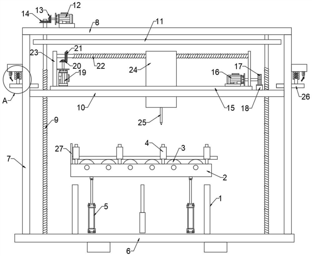
[0027] see Figure 1-5 , an automatic welding device for vehicle thermoformed floor beams, including a support base plate 6 and support plates 1 arranged on the support base plate 6 and symmetrically distributed, and an auxiliary moving mechanism for assisting floor movement is provided above the support plate 1, so A welding torch head 25 is arranged above the auxiliary moving mechanism. The welding torch head 25 is connected to a welding body 24 that controls its welding. The welding body 24 is connected to a space moving mechanism that drives it to move in three directions perpendicular to each other.

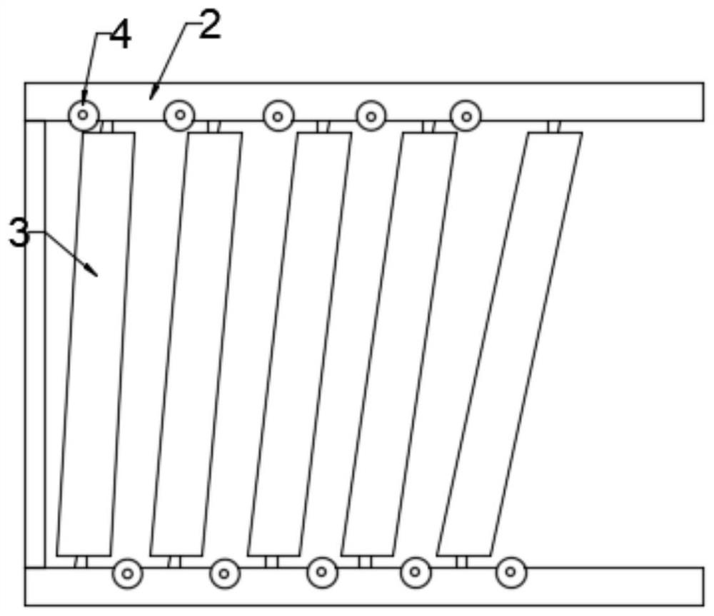
[0028] In this embodiment, the auxiliary moving mechanism includes two symmetrically arranged conveying platforms 2, and evenly distributed unpowered rollers 3 are connected between the two conveying platforms 2 through bearing rotation, and the two sides of the unpowered rollers 3 There are unpowered rollers 4 installed on the transmission platform 2, and the transmission p...

Embodiment 2

[0035] This embodiment has been expanded on the basis of Embodiment 1. A limiting plate 26 slidingly connected with each group of said poles 7 is provided. The limiting plate 26 is located above the lifting support plate 10, and the limiting plate 26 is fixed. Connected with a nesting rod 28, the nesting rod 28 is slidably connected with a fixed sleeve 29, the fixed sleeve 29 is provided with a chute 31 for matching, the chute 31 is elastically connected with the bottom of the nested rod 28 through an elastic member 32, and the fixed sleeve 29 is fixedly connected with a fixed seat 30 fixedly connected with the pole 7, and a travel switch 33 is installed on the fixed seat 30, and the travel switch 33 is electrically connected with the first driving motor 12, and the travel switch 33 is connected with a travel lever 34 that triggers its signal , the movable end of the stroke rod 34 faces the limit plate 26 and is lower than the lower end surface of the fixed sleeve 29. When the ...


PUM


Abstract

The invention discloses an automatic welding device for vehicle thermal forming floor cross beam. The automatic welding device comprises a supporting bottom plate and supporting plates which are arranged on the supporting bottom plate and symmetrically distributed, an auxiliary moving mechanism used for assisting a floor in moving is arranged above the supporting plates, a welding gun head is arranged above the auxiliary moving mechanism, the welding gun head is connected with a welding body controlling the welding gun head to conduct welding, and the welding body is connected with a space moving mechanism driving the welding body to move in three perpendicular directions. By arranging the space moving mechanism and the auxiliary moving mechanism, the floor can be quickly and accurately positioned, then all points of the floor can be accurately welded through the space moving mechanism, and the welding device is quick, convenient to use and high in automation degree; and by arranging alimiting plate, a lifting supporting plate can be reset, a first driving motor does not need to be manually controlled to move all the time, trouble is saved, convenience is achieved, and the automation degree is high.

Description

technical field [0001] The invention relates to the field of welding, in particular to an automatic welding device for thermoforming floor beams of vehicles. Background technique [0002] After the vehicle is thermoformed, the crossbeam needs to be welded for subsequent processing and assembly. The existing welding method generally adopts manual welding through a welding machine. Due to the large floor area and the need for solder joints everywhere, when welding, It is necessary to constantly move the position of the floor to facilitate welding by the welder, which is time-consuming and laborious, and the work efficiency is low. Contents of the invention [0003] The object of the present invention is to provide an automatic welding device for thermoformed floor beams of a vehicle, so as to solve the problems raised in the above-mentioned background technology. [0004] To achieve the above object, the present invention provides the following technical solutions: [0005...

Claims


Application Information

Patent Timeline
IPC IPC(8): B23K31/02B23K37/02B23K37/00B23K37/04
CPCB23K31/02B23K37/0252B23K37/00B23K37/0426
Inventor 蔡育贤
Owner 长春一汽四环力达冲压制品有限公司
Why Eureka
Try Eureka