
Welding machine

A welding machine and welding mechanism technology are applied to the welding machine. It can solve the problems that affect the price and quality, and the movement is prone to errors, so as to avoid multiple positioning and ensure the price and quality.

Pending Publication Date: 2021-02-26
万廷刚
View PDF1 Cites 0 Cited by
  • Summary
  • Abstract
  • Description
  • Claims
  • Application Information

AI Technical Summary

Problems solved by technology

[0005] Aiming at the deficiencies of the prior art, the present invention provides a welding machine, which can solve the problem that during the use of the existing welding machine, the welded product needs to be continuously adjusted to the welding position, which is basically manually operated, and each welding The equipment needs to be re-run, and the movement between each other is prone to errors, which affects the price and quality of the problem

Method used


Image

  • Welding machine
  • Welding machine
  • Welding machine

Examples


Embodiment

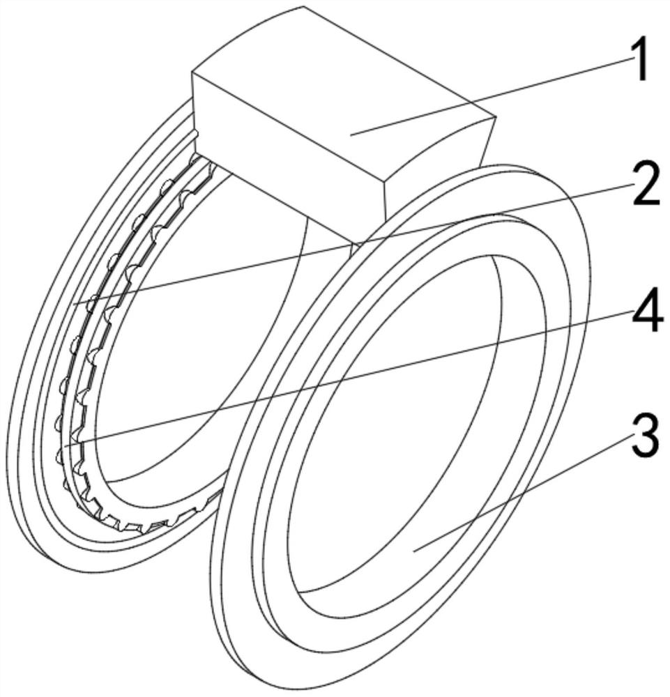
[0041] see Figure 1-7 , the present invention provides a technical solution: a welding machine, including a welding mechanism 1, an external power supply mechanism 2 is movably connected to the middle and lower positions of the outer walls on both sides of the welding mechanism 1, and the side of the external power supply mechanism 2 away from the welding mechanism 1 is fixedly connected to a Limiting the driving mechanism 3, the outer surface of the limiting driving mechanism 3 close to the external power supply mechanism 2 is movably connected with a trigger mechanism 4;

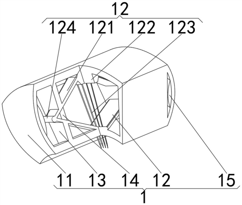
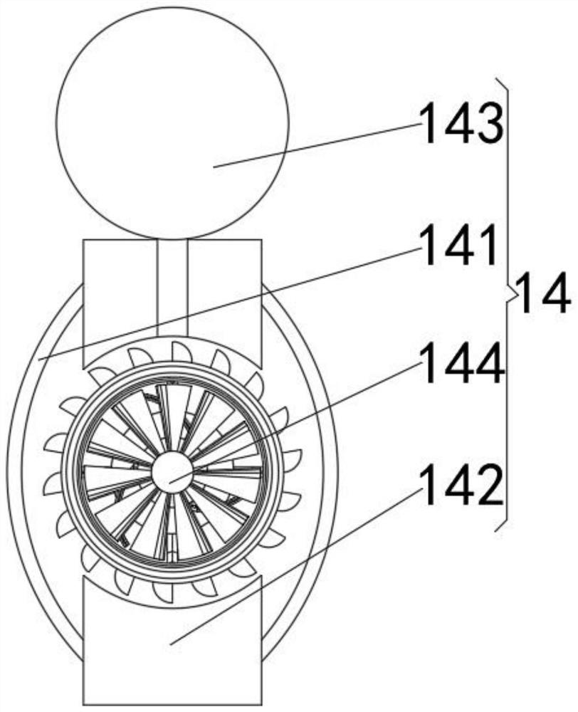
[0042] The welding mechanism 1 includes a welding box 11. A rhombus welding mechanism 12 is arranged in the middle of the inner cavity of the welding box 11. The inner cavity of the welding box 11 is located on both sides of the rhombus welding mechanism 12 and is fixedly connected with a partition plate 13. The two sides of the inner cavity of the rhombus welding mechanism 12 A temperature control mechan...


PUM


Abstract

The invention discloses a welding machine comprising a welding mechanism, and external power supply mechanisms are movably connected with the lower middle positions of the outer walls of the two sidesof the welding mechanism; limiting driving mechanisms are fixedly connected with the sides, away from the welding mechanism, of the external power supply mechanisms, and triggering mechanisms are movably connected with the outer surfaces of the sides, close to the external power supply mechanisms, of the limiting driving mechanisms. the welding mechanism comprises a welding box, and a rhombus welding mechanism is arranged in the middle of an inner cavity of the welding box; partition plates are fixedly connected with the positions, located on the two sides of the rhombus welding mechanism, ofthe inner cavity of the welding box, and temperature control mechanisms are fixedly connected with the positions, located on the partition plates, of the two sides of an inner cavity of the rhombus welding mechanism; and the middle positions of the inner walls of the two sides of the welding box are fixedly connected with arc-shaped electrifying blocks. The invention relates to the technical field of welding. Change of relative position is achieved through movement of the welding mechanism, welding is completed through one-time location, repeated locations are avoided, and the price and quality are guaranteed.

Description

technical field [0001] The invention relates to the technical field of welding, in particular to a welding machine. Background technique [0002] With the development of modern industry, automated production is becoming more and more popular, automated production equipment has also been more widely used, and the degree of automation of equipment is getting higher and higher, and the accuracy requirements of production equipment are also increasing. high. [0003] According to Chinese CN209936165U, a welding device includes a frame, the frame is provided with a welding torch and a welding fixture, the welding fixture is arranged at the bottom of the welding torch, the welding torch is provided with a positioning hole for accommodating the rivet, and the axis of the positioning hole is arranged along the up and down direction , the welding fixture includes a base plate connected to the frame, a positioning mold and a positioning piece arranged on the top of the base plate, th...

Claims


Application Information

Patent Timeline
IPC IPC(8): B23K31/02B23K37/00
CPCB23K31/02B23K37/00
Inventor 万廷刚
Owner 万廷刚
Learn More