Clamping plate used in bolt lead angle forming process

A technology of bolts and splints, applied in the field of splints used in the process of bolt opening angles, can solve problems such as unreliable bolt fixing, achieve the effect of preventing bolts from falling off and increasing the degree of firmness

Active Publication Date: 2021-02-26
安徽凯瑞汽配制造有限公司
View PDF10 Cites 0 Cited by
  • Summary
  • Abstract
  • Description
  • Claims
  • Application Information

AI Technical Summary

Problems solved by technology

However, most of the existing fixing splints are fixed on both sides when fixing their bolts, which is not reliable for bolt fixing.

Method used


Image

  • Clamping plate used in bolt lead angle forming process
  • Clamping plate used in bolt lead angle forming process
  • Clamping plate used in bolt lead angle forming process

Examples


Embodiment Construction

[0020] The following will clearly and completely describe the technical solutions in the embodiments of the present invention with reference to the accompanying drawings in the embodiments of the present invention. Obviously, the described embodiments are only some, not all, embodiments of the present invention. Based on the embodiments of the present invention, all other embodiments obtained by persons of ordinary skill in the art without making creative efforts belong to the protection scope of the present invention.

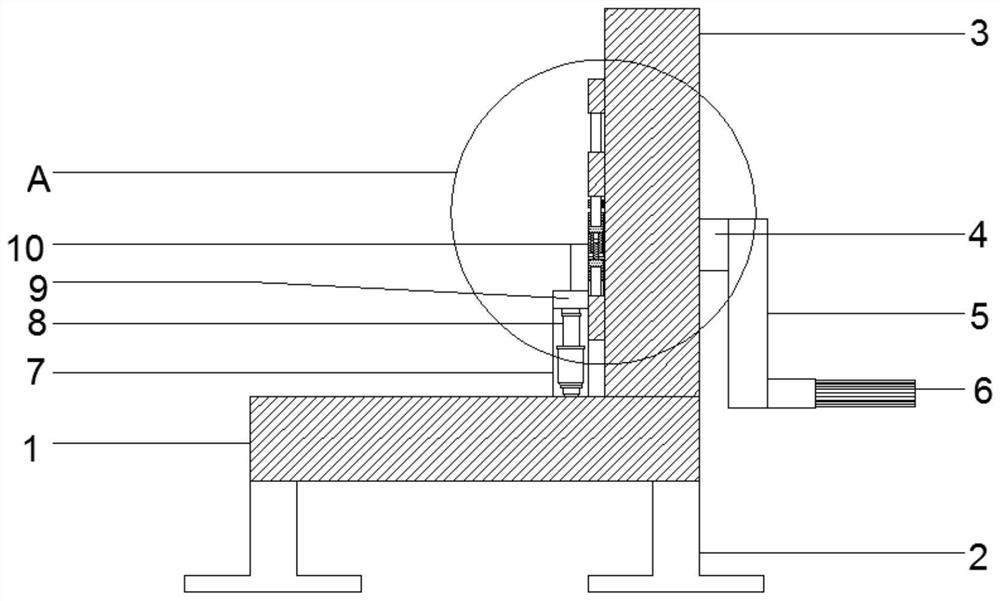
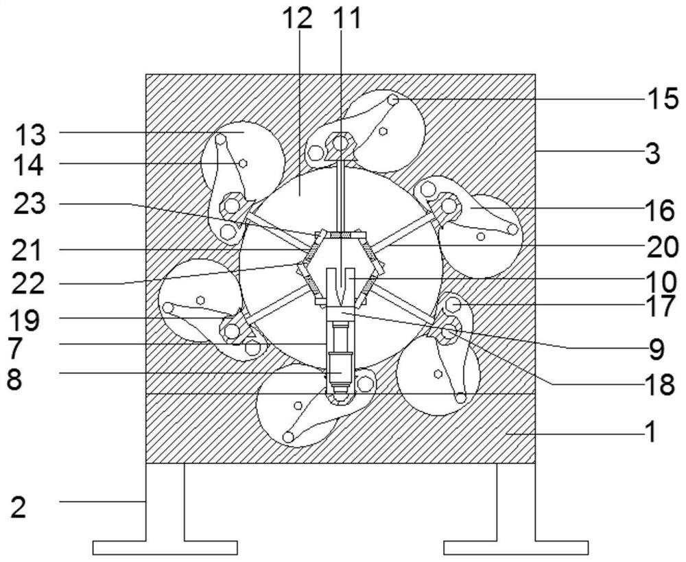
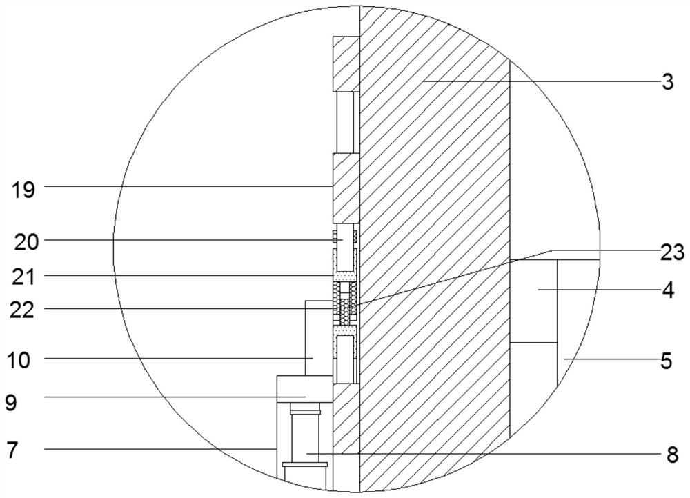
[0021] see Figure 1~4 , in an embodiment of the present invention, a splint used in the process of bolt opening angle, including a base 1, the lower end of the base 1 is fixedly installed with support feet 2, the support feet 2 are fixedly installed at the four corners of the lower end of the base 1, and the upper end of the base 1 The rear side is fixedly installed with a device plate 3, and the front side of the device plate 3 is provided with a fixed plate...


PUM


Abstract

The invention discloses a clamping plate used in the bolt lead angle forming process. The clamping plate comprises a base. Supporting feet are fixedly mounted at the lower end of the base and fixedlymounted at the four corners of the lower end of the base. A device plate is fixedly mounted on the rear side of the upper end of the base. A first fixing plate is arranged on the front side of the device plate. An air cylinder is fixedly mounted in the first fixing plate. A supporting plate is fixedly mounted at the upper end of the air cylinder. Arc-shaped plates are fixedly mounted on the rear side of the upper end of the supporting plate in a bilateral symmetry manner. A V-shaped groove is formed between the two arc-shaped plates. A first fixing shaft is fixedly mounted in the middle of therear end of the device plate. A first connecting rod is fixedly mounted at the rear end of the first fixing shaft. A grip is fixedly mounted on the lower portion of the rear end of the first connecting rod. A first gear is fixedly mounted in the middle in the device plate, and the first gear corresponds to the first fixing shaft. When the clamping plate is used, a rectangular groove and a first supporting plate are correspondingly clamped, and the situation that the diameter of a bolt is too small, the clamping model is too large, and clamping force cannot be provided is prevented.

Description

technical field [0001] The invention relates to a splint, in particular to a splint used in the process of opening angles of bolts. Background technique [0002] The lead angle refers to the angle between the tangent of the helix and the plane perpendicular to the thread axis, also known as the lead angle. The lead angle of the thread line varies at different diameters of the thread, and is usually calculated at the pitch diameter of the thread. The lead angle is the thread lead angle, the angle between the tangent of the helix on the middle diameter cylinder and the plane perpendicular to the thread axis, which affects the self-locking and anti-loosening of the thread. And what existing most fixed splints adopted when fixing its bolt all is the two-side fixing mode, is not firm for bolt fixing like this. Therefore, those skilled in the art provide a splint used in the process of opening the angle of the bolt to solve the problems raised in the above-mentioned background t...

Claims


Application Information

Patent Timeline
IPC IPC(8): B23Q3/06B25B11/00
CPCB23Q3/06B25B11/00
Inventor 李林峰
Owner 安徽凯瑞汽配制造有限公司
Why Eureka
Try Eureka