
Device for punching pipe orifice of plastic pipe

A plastic pipe, punching technology, applied in metal processing and other directions, can solve the problems of low punching efficiency and easy hand injury, and achieve the effect of improving punching efficiency

Active Publication Date: 2021-02-26
任丘市华信电信器材有限公司
View PDF9 Cites 0 Cited by
  • Summary
  • Abstract
  • Description
  • Claims
  • Application Information

AI Technical Summary

Problems solved by technology

[0005] In order to overcome the disadvantages of low punching efficiency and easy hand injury, the present invention needs to manually put in and take out the plastic pipes repeatedly to punch the nozzle. The technical problem to be solved by the invention is to provide an , The equipment for punching the mouth of plastic pipes that can protect hands

Method used


Image

  • Device for punching pipe orifice of plastic pipe
  • Device for punching pipe orifice of plastic pipe
  • Device for punching pipe orifice of plastic pipe

Examples


Embodiment 1

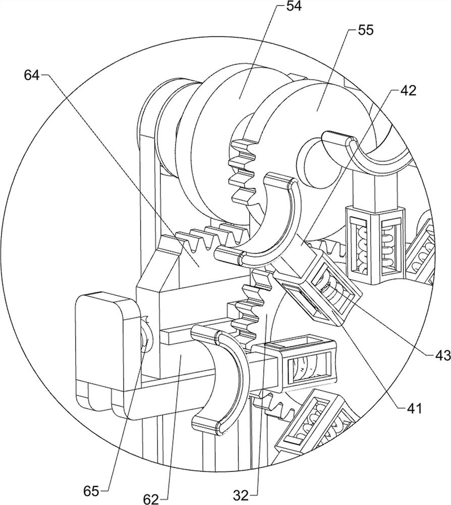
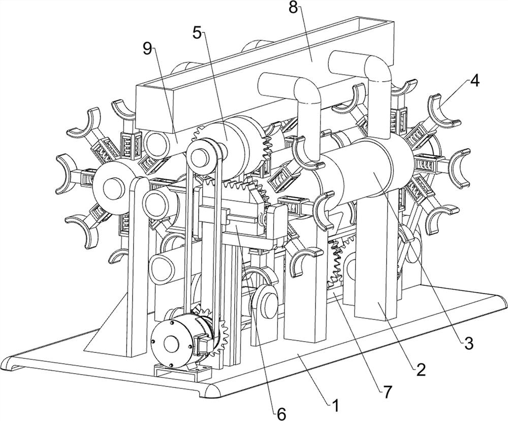
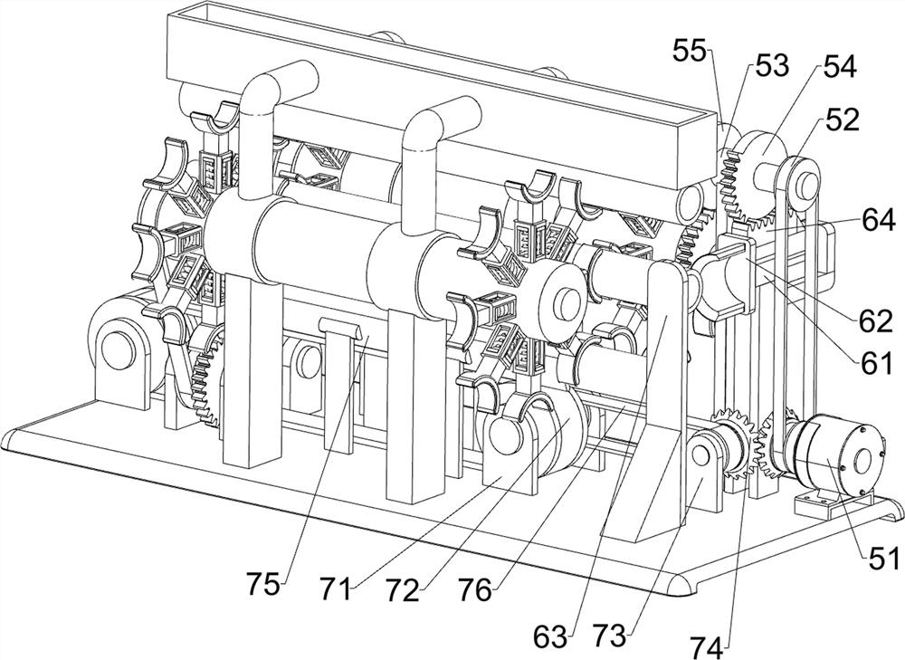
[0025] A device for punching the mouth of plastic pipes, such as Figure 1-4 As shown, it includes a base plate 1, a support frame 2, a rotating mechanism 3, a clamping mechanism 4, a driving mechanism 5 and a punching mechanism 6. Two support frames 2 are connected symmetrically on the front and rear sides of the top of the base plate 1, and the base plate 1 A rotating mechanism 3 is installed between the supporting frame 2, a clamping mechanism 4 is installed on the rotating mechanism 3, a driving mechanism 5 is installed on the top of the bottom plate 1, the driving mechanism 5 is connected to the rotating mechanism 3, and a punching mechanism is installed on the top of the bottom plate 1 6. The punching mechanism 6 is in transmission connection with the driving mechanism 5 .

[0026] The rotating mechanism 3 includes a rotating shaft rod 31, a transmission gear 32, a first transmission belt group 33, a first mounting base 34 and a driving gear 35, and a rotating shaft rod ...

Embodiment 2

[0032] On the basis of Example 1, such as image 3As shown, a transmission mechanism 7 is also included, and the transmission mechanism 7 includes a second mounting seat 71, a conveyor belt group 72, a third mounting seat 73, a bevel gear 74 group, a limit plate 75 and a third transmission belt group 76, and the bottom plate 1. The left and right sides of the top are connected with the second mounting base 71, and the conveyor belt group 72 is rotatably connected between the two second mounting bases 71. The left side of the bottom plate 1 is connected with the third mounting base 73. The third mounting base 73 Located on the left side of the second mount 71 on the left side, the third mount 73 is rotatably connected with a bevel gear 74, and the output shaft of the servo motor 51 is also connected with a bevel gear 74, and the two bevel gears 74 mesh with each other. A third drive belt set 76 is connected between the drive shaft of the bevel gear 74 on the seat 73 and the dri...

Embodiment 3

[0035] On the basis of Example 2, such as figure 1 As shown, it also includes a pipe feed position calibration frame 8, and the pipe feed position calibration frame 8 is connected between the tops of the four support frames 2.

[0036] The plastic pipe 9 can be put into the pipe feed position calibration frame 8, and the plastic pipe 9 falls on the clamp arm 42 through the pipe feed position calibration frame 8, so that the plastic pipe 9 can be adjusted by the pipe feed position calibration frame 8. The position is calibrated, thereby being able to facilitate punching the mouth of the plastic pipe 9.


PUM


Abstract

The invention relates to a device for punching a pipe orifice, and particularly relates to a device for punching a pipe orifice of a plastic pipe. The device for punching the pipe orifice of the plastic pipe can improve the punching efficiency and protect hands. The device for punching the pipe orifice of the plastic pipe comprises a bottom plate, a rotating mechanism, a clamping mechanism and a driving mechanism, wherein four supporting frames are connected to the bottom plate; the rotating mechanism is arranged between the bottom plate and the supporting frames; the clamping mechanism is arranged on the rotating mechanism; and the driving mechanism is arranged on the bottom plate, and the driving mechanism is in transmission connection with the rotating mechanism. According to the device, the driving mechanism can drive all the mechanisms to work, the rotating mechanism and the clamping mechanism are matched so that the plastic pipe can be conveyed to a punching mechanism, the pipe orifice of the plastic pipe can be punched through the punching mechanism, the punched plastic pipe can be clamped and fixed through the clamping mechanism, and therefore the effect of protecting the hands can be achieved.

Description

technical field [0001] The invention relates to a device for punching the mouth of a pipe, in particular to a device for punching the nozzle of a plastic pipe. Background technique [0002] In order to change the direction of the plastic pipes and butt them together, it is necessary to punch the mouth of the butt plastic pipes to facilitate the butt joint of the plastic pipes. At present, the plastic pipes are usually manually put into the mouth punching equipment, and then To remove the punched plastic pipe from the punching equipment, it is necessary to manually put in and take out the plastic pipe repeatedly, which takes a lot of time and energy, resulting in low punching efficiency, and in the process , if you are not careful, your hands will be easily injured. [0003] Therefore need to research and develop a kind of equipment that can improve punching efficiency, can protect hand and be used for the punching shape of plastic pipe nozzle. Contents of the invention ...

Claims


Application Information

Patent Timeline
IPC IPC(8): B26D3/16B26D7/02
CPCB26D3/166B26D7/02B26D2007/013
Inventor 窦海霞
Owner 任丘市华信电信器材有限公司
Learn More