Cantilever type light overhead line system suspension system positioning device
A suspension system and positioning device technology, applied in the direction of overhead lines, etc., can solve the problems of environmental impact, large electrification range, complex structure, etc., and achieve the effect of reducing the number of parts, reducing environmental damage, and simplifying the structure and composition.
- Summary
- Abstract
- Description
- Claims
- Application Information
AI Technical Summary
Problems solved by technology
Method used
Image

Examples
Embodiment 1
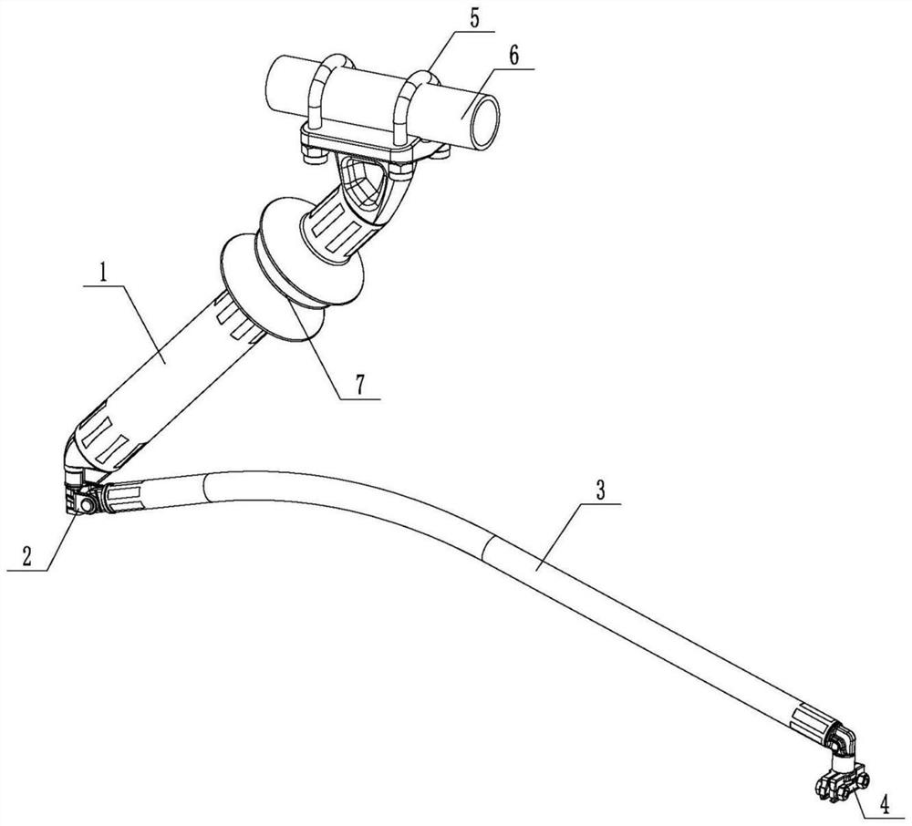
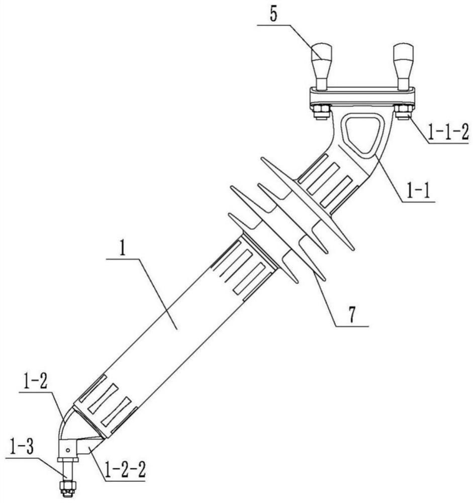
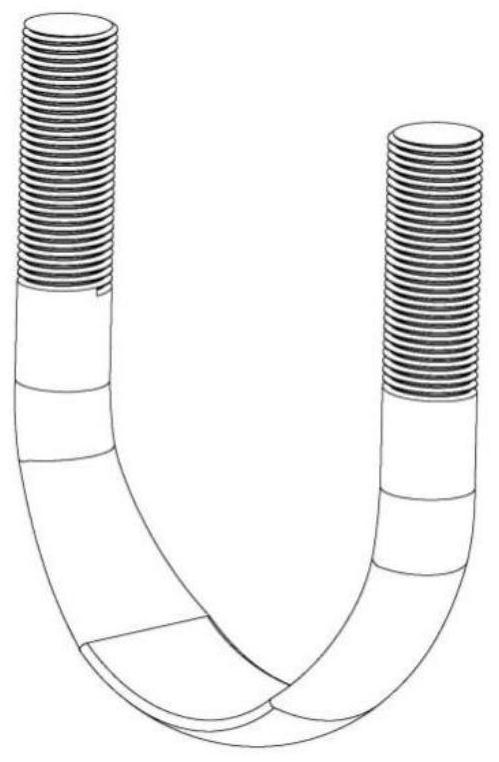
[0037] See also Figure 1 to Figure 8 , the embodiment of the present invention specifically provides a positioning device for a cantilever light catenary suspension system. The positioning device is applied to a place with a single contact line, and specifically includes: positioning connector 1, rotating ears 2, positioner 3, positioning line clamp 4 and U-shaped bolt 5, wherein the upper end of the positioning connector 1 is fixedly connected with a connecting seat 1-1, and the U-shaped bolt 5 is arranged opposite to the connecting seat 1-1 and connected to the connecting seat 1-1; the rotating double ear 2 Vertically hinged at the lower end of the positioning connector 1, one end of the positioner 3 is horizontally hinged with the rotating double ear 2, and its other end is fixedly connected with the positioning clamp 4.
[0038] The connecting seat 1-1 is crimped and fixed with the positioning connector 1 through the crimping process through the first annular groove 1-1-1...
Embodiment 2
[0046] See also Figure 2 to Figure 11 , the embodiment of the present invention provides a positioning device for a cantilever light catenary suspension system. The positioning device is applied to a place with double contact wires, and specifically includes: positioning connector 1, rotating ears 2, positioner base 8, two Positioner 3, two positioning clamps 4 and U-shaped bolts 5, wherein the upper end of positioning connector 1 is fixedly connected with connecting seat 1-1, and U-shaped bolt 5 is arranged opposite to connecting seat 1-1 and connected to connecting seat 1 -1, the locator base 8 is fixed at the lower end of the positioning connector 1, the rotating ears 2 are respectively vertically hinged at both ends of the locator base 8, and one end of the two locators 3 is respectively horizontally hinged with the rotating ears 2, and The other ends are respectively fixedly connected with the corresponding positioning clamps 4 .
[0047] The connecting seat 1-1 is crim...
PUM
 Abstract
Description
Claims
Application Information