Pressure type rotational-flow air floatation separation equipment for treating oily wastewater
A swirl air flotation and wastewater treatment technology, applied in water/sewage treatment equipment, water/sewage treatment, flotation water/sewage treatment, etc., can solve the problems of low power, affecting separation effect, small contact area between oil and air, etc. , to achieve the effect of improving efficiency and increasing power
- Summary
- Abstract
- Description
- Claims
- Application Information
AI Technical Summary
Problems solved by technology
Method used
Image

Examples
Embodiment 1
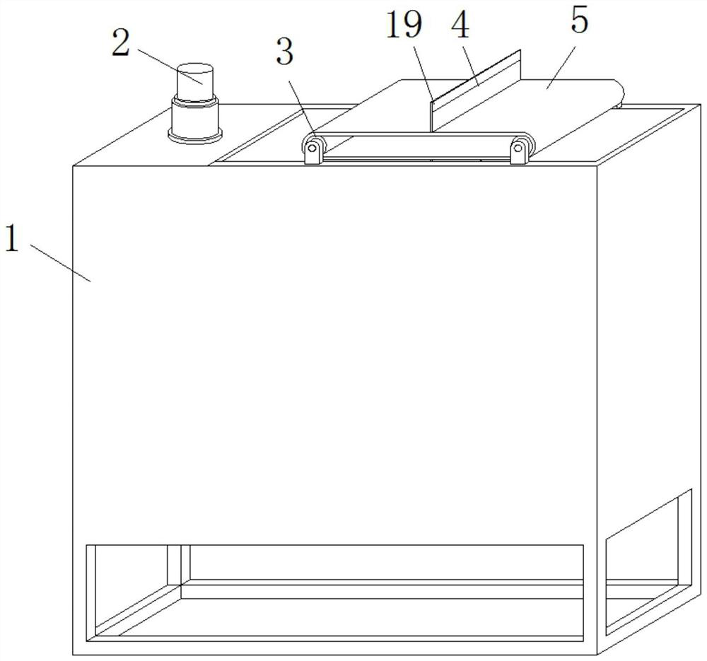
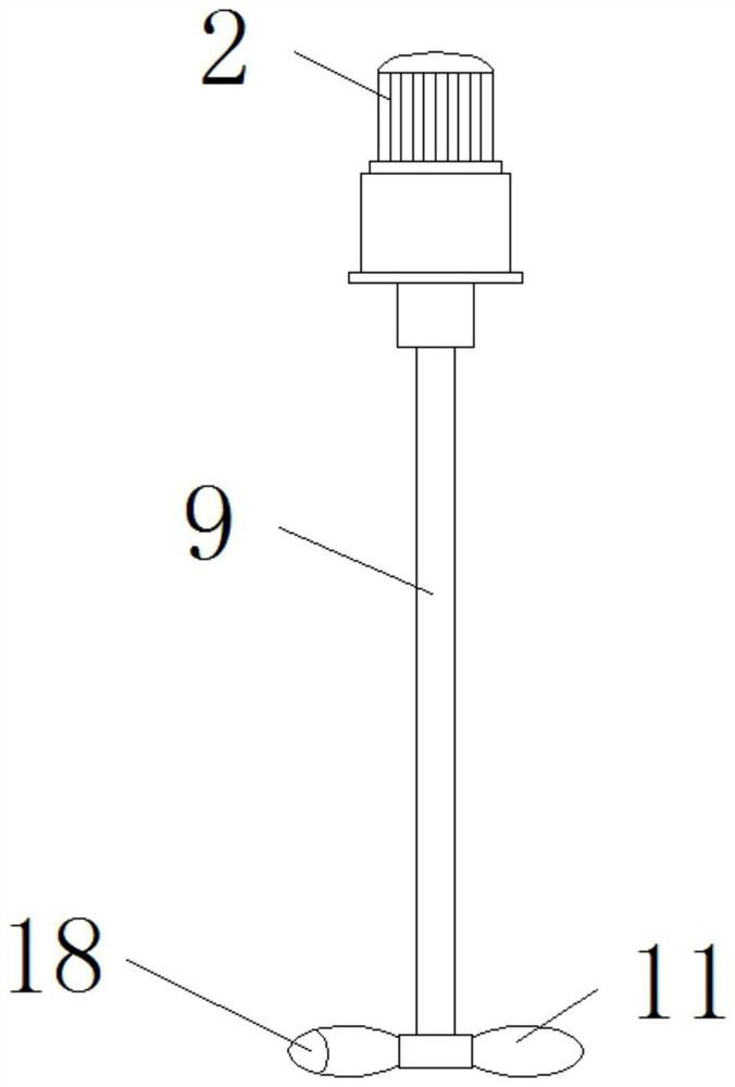
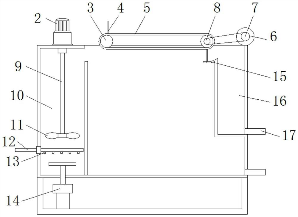
[0023] see figure 1 , figure 2 , image 3 , in an embodiment of the present invention, a pressure-type cyclone air flotation separation device for oily wastewater treatment includes a separation pool 1; The bottom of 16 and the bottom of separation tank 1 are all provided with a drain pipe 17, and the drain pipe 17 is welded to the bottom of the collection tank 16 or the bottom of the separation tank 1, and the two sides of the upper end of the separation tank 1 are provided with a rotating shaft 3, and the outer sleeve of the rotating shaft 3 There is a conveyor belt 5, and scrapers 4 are arranged on both sides of the conveyor belt 5. The scrapers 4 are fixed and installed on the upper side of the conveyor belt 5 by bolts. Bearing, one end of the rotating shaft 3 passes through the outer side of the separation tank 1 to be provided with a pulley 8, the pulley 8 is fixedly installed on one side of the rotating shaft 3 by bolts, and the upper side of the separation tank 1 is...
Embodiment 2
[0031] see figure 1 , figure 2 , image 3, in an embodiment of the present invention, a pressure-type cyclone air flotation separation device for oily wastewater treatment includes a separation pool 1; The bottom of 16 and the bottom of separation tank 1 are all provided with a drain pipe 17, and the drain pipe 17 is welded to the bottom of the collection tank 16 or the bottom of the separation tank 1, and the two sides of the upper end of the separation tank 1 are provided with a rotating shaft 3, and the outer sleeve of the rotating shaft 3 There is a conveyor belt 5, and scrapers 4 are arranged on both sides of the conveyor belt 5. The scrapers 4 are fixed and installed on the upper side of the conveyor belt 5 by bolts. Bearing, one end of the rotating shaft 3 passes through the outer side of the separation tank 1 to be provided with a pulley 8, the pulley 8 is fixedly installed on one side of the rotating shaft 3 by bolts, and the upper side of the separation tank 1 is ...
PUM
 Abstract
Description
Claims
Application Information
 - R&D Engineer
- R&D Manager
- IP Professional
- Industry Leading Data Capabilities
- Powerful AI technology
- Patent DNA Extraction
Browse by: Latest US Patents, China's latest patents, Technical Efficacy Thesaurus, Application Domain, Technology Topic.
© 2024 PatSnap. All rights reserved.Legal|Privacy policy|Modern Slavery Act Transparency Statement|Sitemap