Automatic yarn bobbin feeding and discharging device with stable structure

A technology of automatic loading and unloading and stable structure, which is applied in the direction of textiles and papermaking, can solve the problems of dwelling, inability to control the depth accurately, and inability to conveniently replenish yarn bobbins, etc., and achieve high feasibility, stable structure, and improved reliability Effect

Inactive Publication Date: 2021-02-26
江涛
View PDF11 Cites 0 Cited by
  • Summary
  • Abstract
  • Description
  • Claims
  • Application Information

AI Technical Summary

Problems solved by technology

[0004] However, this structure is used to cover the delivery rod of the yarn bobbin without a stable and effective support structure, and when it is fixedly connected with the delivery pipeline, it will not be possible to conveniently replenish the yarn bobbin
Moreover, the yarn bobbin may stay on the delivery rod due to friction, in addition, the depth of the yarn bobbin sleeved on the spindle cannot be precisely controlled

Method used


Image

  • Automatic yarn bobbin feeding and discharging device with stable structure
  • Automatic yarn bobbin feeding and discharging device with stable structure
  • Automatic yarn bobbin feeding and discharging device with stable structure

Examples


Embodiment Construction

[0083] The following description serves to disclose the present invention to enable those skilled in the art to carry out the present invention. The preferred embodiments described below are only examples, and those skilled in the art can devise other obvious variations.

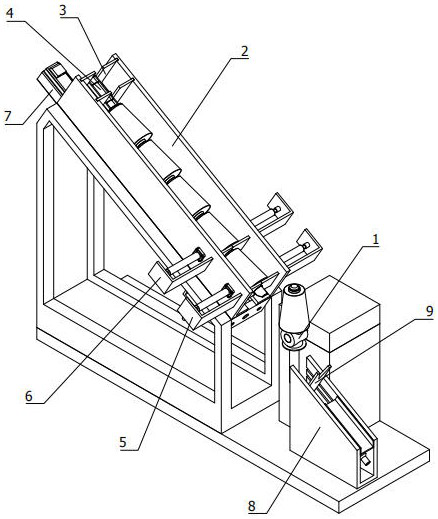
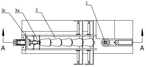
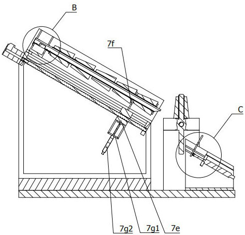
[0084] Such as figure 1 As shown, a yarn bobbin automatic loading and unloading device with a stable structure includes a bidirectional turning spindle 1, a feeding bin 2, a shaft hanger 3, a mounting shaft 4, a first stopper mechanism 5, and a second stopper Mechanism 6, pushing mechanism 7, unloading rack 8 and stripping mechanism 9;

[0085] Two-way reversing spindle 1, rotatably installed on the frame, used to install the yarn bobbin;

[0086] The upper material bin 2 is obliquely arranged on one side of the bidirectional reversible spindle 1, and is collinear with the axis of the bidirectional reversible spindle 1 in the working state;

[0087] The shaft body hanger 3 is plugged with one end of the u...


PUM


Abstract

The invention relates to the field of yarn coating equipment, in particular to an automatic yarn bobbin feeding and discharging device with a stable structure. The automatic yarn bobbin feeding and discharging device comprises a bidirectional turnover spindle, a feeding bin, a shaft body hanging frame, a mounting shaft, first material blocking mechanisms, second material blocking mechanisms, a pushing mechanism, a discharging frame and a stripping mechanism, wherein the bidirectional turnover spindle is rotatably mounted on the rack; the feeding bin is obliquely arranged on one side of the bidirectional turnover spindle; the shaft body hanging frame is matched with one end of the feeding bin in an inserted mode; the mounting shaft is clamped with the working end of the shaft body hanging frame, and is used for mounting a plurality of yarn bobbins along the axis direction; the first material blocking mechanisms are symmetrically installed on the two sides of the feeding bin; the secondmaterial blocking mechanisms are symmetrically arranged on the two sides of the feeding bin, and the second material blocking mechanisms and the first material blocking mechanisms are distributed at intervals; the pushing mechanism is installed at the bottom of the feeding bin; the discharging frame is arranged on the other side of the bidirectional turnover spindle and is opposite to the feedingbin; and the stripping mechanism is obliquely arranged at the upper end of the discharging frame. According to the scheme, yarn bobbins are supplemented conveniently, the structure is stable and reliable, control is convenient, and working efficiency is high.

Description

technical field [0001] The invention relates to the field of yarn covering equipment, in particular to an automatic loading and unloading device for yarn barrels with stable structure. Background technique [0002] In the prior art, on the yarn coating equipment in the textile industry, the upper and lower yarn bobbins are all manually operated, which is inefficient and may easily cause equipment shutdown and affect production capacity. [0003] Chinese patent CN201821966293.9 discloses an automatic loading and unloading device for yarn bobbins of yarn coating equipment, which includes a conveying pipe, which is arranged obliquely, and a conveying core rod is arranged inside the conveying pipe, along the upper side wall of the lower end of the conveying pipe. Two cylinders are arranged at intervals in the axial direction, a No. 1 baffle is connected to the No. 1 cylinder, a No. 2 baffle is connected to the No. 2 cylinder, and a No. 1 through hole is set on the side wall of t...

Claims


Application Information

Patent Timeline
Patent Type & Authority Applications(China)
IPC IPC(8): D01H9/18
CPCD01H9/18
Inventor 江涛
Owner 江涛
Why Eureka
Try Eureka