Water-saving pressure type pure flat closestool base

A pressure type, pure flat technology, applied in water supply equipment, flushing toilets, buildings, etc., can solve the problems that the flushing effect cannot be significantly improved, the wall of the urinal is difficult to fully flush, and the wall of the urinal is no longer smooth, so as to avoid Effects of dirt retention, improved flushing effect, and waste reduction

Pending Publication Date: 2021-02-26
ECO XIAMEN TECH INC
View PDF1 Cites 0 Cited by
  • Summary
  • Abstract
  • Description
  • Claims
  • Application Information

AI Technical Summary

Problems solved by technology

However, this kind of flushing water structure makes it difficult for the wall of the urinal to be fully flushed. For this reason, a rotary flushing toilet is designed in the industry (see Chinese Patent No. CN201502098U), and a spiral surrounding guide is set on the side wall of the urinal. Surface, in the process of spraying water in the flushing ring, flush down in a spiral direction along the guide surface
This structure cannot significantly improve the flushing effect in actual use. On the contrary, because the design of the guide surface protrudes from the wall of the urinal, the wall of the urinal is no longer smooth, and it is easier to store dirt and dirt, and often results in retention of dirt. Conditions at the bottom of the pool

Method used


Image

  • Water-saving pressure type pure flat closestool base
  • Water-saving pressure type pure flat closestool base
  • Water-saving pressure type pure flat closestool base

Examples


Embodiment Construction

[0025] In order to further explain the technical solution of the present invention, the present invention will be described in detail below through specific examples.

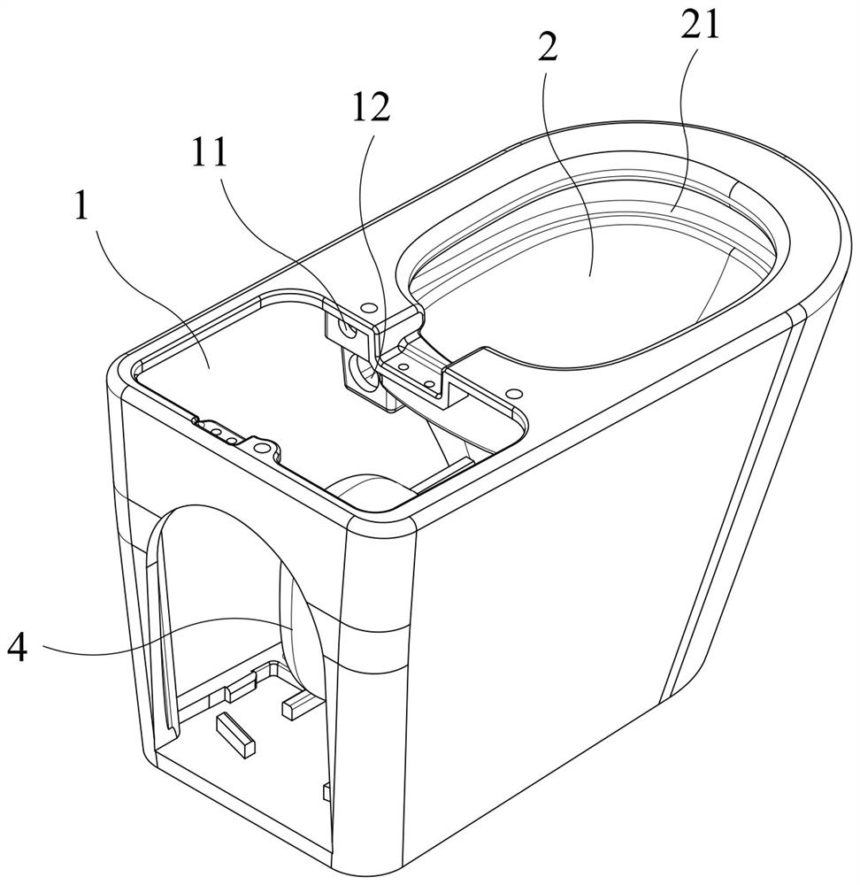
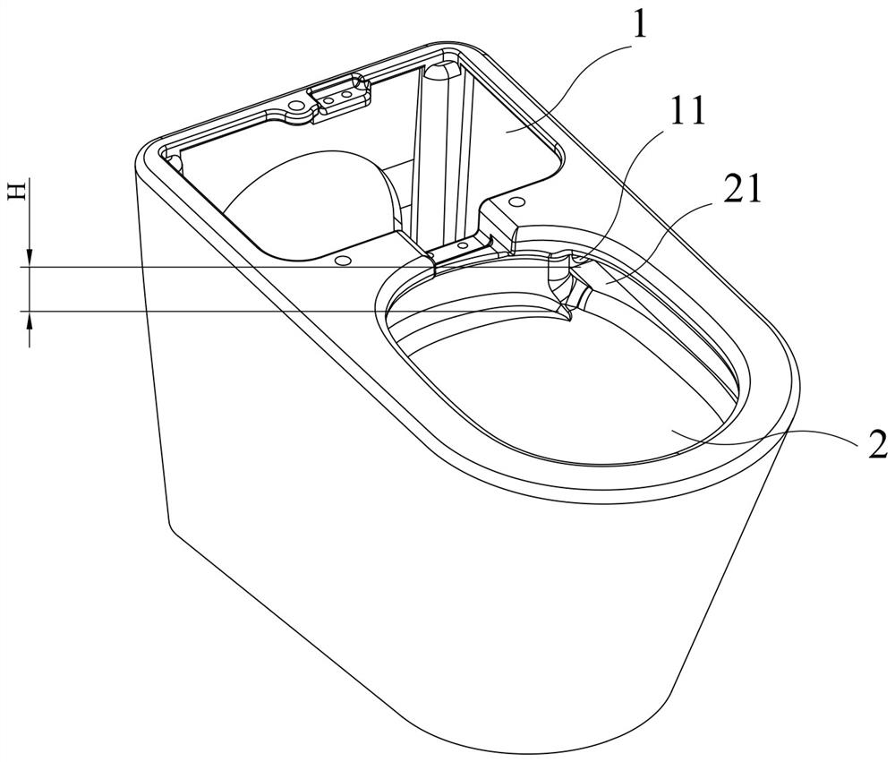
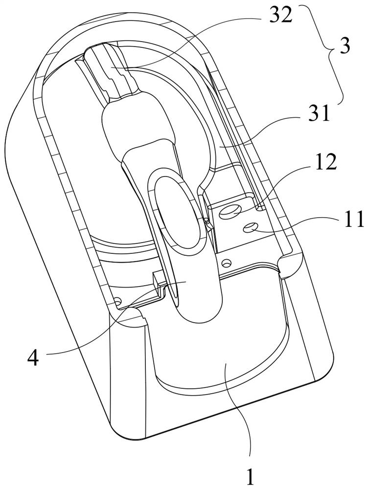
[0026] The present invention is a water-saving pressure-type flat toilet base, which includes an accommodating cavity 1 and a urinal 2 arranged front and back, as well as a main flushing pipeline 3 and a sewage discharge pipeline 4 .

[0027] The accommodating cavity 1 is provided with punching ring holes 11 and main punching holes 12;

[0028] The top of the urinal 2 is provided with a water-guiding step 21, and the water-guiding step 21 is arranged in a ring along the wall of the urinal 2 and its height gradually decreases, and its starting end is set opposite to the flushing ring hole 11; the bottom of the urinal 2 is provided with Sewage outlet 22;

[0029] The main flushing pipe 3 is arranged around the outer periphery of the urinal 2, and includes a horizontal delay section 31 and an obliquely arranged d...


PUM


Abstract

The invention discloses a water-saving pressure type pure flat closestool base which comprises a containing cavity and a urinal which are arranged front and back, a main flushing pipeline and a blow-off pipeline. The containing cavity is provided with a punching ring hole and a main punching hole; a water guide step is arranged at the top of the urinal, annularly wound along the wall surface of the urinal and gradually reduced in height, and the starting end of the water guide step is opposite to the flushing ring hole; a drain outlet is formed in the bottom of the urinal; the main flushing pipeline is arranged on the periphery of the urinal in a surrounding mode and comprises a horizontally-arranged time delay section and an obliquely-arranged diving section, wherein the time delay section is communicated with the main punching hole, and the diving section is communicated with the bottom of the urinal; and the blow-off pipeline is communicated with the drain outlet. Water flow flowingout of the flushing ring hole is guided through the water guide step, so that vortex flushing ring water is formed to efficiently flush the wall surface of the urinal; the delay section of the main flushing pipeline is used for prolonging the time for main flushing water to reach the bottom of the urinal, thereby ensuring that ring flushing water and the main flushing water are discharged at thesame time, and reducing waste of the main flushing water, and avoiding dirt retention; and the main flushing water is accelerated through the diving section to improve the impact force of the main flushing water, thereby finally improving the flushing effect.

Description

technical field [0001] The invention relates to the technical field of toilets, in particular to a water-saving pressure type flat toilet base. Background technique [0002] The toilet usually relies on the combination of the main flush water and the flush water. The flush water washes away the dirt on the wall of the urinal, and then the main flush water drives the dirt washed down by the flush water to be discharged through the sewage pipe. [0003] The common flushing ring water structure is to set a circle of water channels around the inside of the lip of the toilet, and then arrange a plurality of water outlet holes on the water channel to allow water to flush the urinal of the toilet downward from each water outlet hole. However, this kind of flushing water structure makes it difficult for the wall of the urinal to be fully flushed. For this reason, a rotary flushing toilet is designed in the industry (see Chinese Patent No. CN201502098U), and a spiral surrounding guid...

Claims


Application Information

Patent Timeline
IPC IPC(8): E03D11/06E03D11/08E03D11/13E03D11/17E03D11/18
CPCE03D11/06E03D11/08E03D11/13E03D11/17E03D11/18
Inventor 黄炳兴张东生戴金定
Owner ECO XIAMEN TECH INC
Why Eureka
Try Eureka