Automobile door lock installation structure

An installation structure and a technology for automobile door locks, which are applied in the field of automobile parts installation, can solve the problems of simple rebound structure, inconvenient connection between the lock tongue and the base, lack of linkage mechanism, etc., and achieve the effect of increasing the stability of the connection.

Active Publication Date: 2021-02-26
江苏金鼎汽车锁制造有限公司
View PDF5 Cites 0 Cited by
  • Summary
  • Abstract
  • Description
  • Claims
  • Application Information

AI Technical Summary

Problems solved by technology

[0004] The main purpose of the present invention is to provide a car door lock installation structure, which can effectively solve the problems of simple rebound structure between the lock tongue and the base, inconvenient connection between the lock tongue and the base, and lack of a stable linkage mechanism in the background technology

Method used


Image

  • Automobile door lock installation structure
  • Automobile door lock installation structure
  • Automobile door lock installation structure

Examples


Embodiment 1

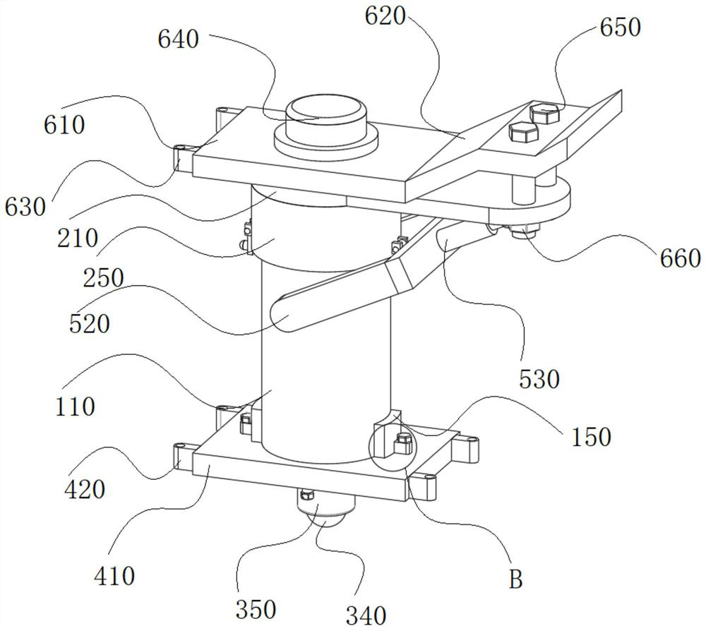
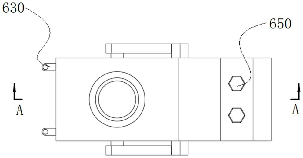
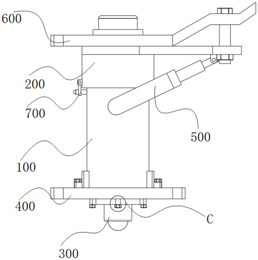
[0035] refer to figure 1 —10, the present invention is a car door lock installation structure, including a deadbolt 100, a base 200, a push mechanism 300, a first installation mechanism 400, a linkage mechanism 500, a second installation mechanism 600 and a locking mechanism 700, the deadbolt 100 includes an outer clamping column 110, an inner clamping column 120, and a fixed block 150. The base 200 includes a bottom plate 210, a mounting column 220, a long column 230, and a long tube 250. Both the outer clamping column 110 and the inner clamping column 120 are hollow structures, and the long column The sides of the 230th circle slide with the inner side of the inner clamping column 120. The pressing mechanism 300 includes a piston plate 330 and a fixed clamping column 350. The fixed clamping column 350 is a hollow structure, and the side of the piston plate 330 slides with the inner circumference of the outer clamping column 110. Cooperate, the lower surface of the inner clam...

Embodiment 2

[0044] The working principle of the present invention is as follows: four sets of slide plates 130 are symmetrically arranged on the outer peripheral side of the inner clamping column 120, and the formed slots just play a limiting role on the push block 240, preventing the push block 240 from compressing the return spring 140. Due to the lack of limit, there is a problem of difficulty in compression. A through hole is provided inside the inner clamping column 120. During the travel process of the push block 240 compressing the return spring 140, the long column 230 slides and fits with the through hole, which is also conducive to compression. Stable, the rotation and cooperation between the rotating ring 730 and the fixed card seat 710 can easily change the locking angle of the locking plate 740, mainly according to the linkage mechanism 500 to adjust the locking angle. Compared with the traditional locking structure, the locking plate The way of sliding connection between 740 ...


PUM


Abstract

The invention relates to the technical field of automobile part installment, in particular to an automobile door lock installation structure. The structure comprises a spring bolt, a base, a pressingmechanism, a first installation mechanism, a linkage mechanism, a second installation mechanism and a locking mechanism; the spring bolt comprises an outer clamping column, an inner clamping column and a fixed block; the base comprises a bottom plate, an installation column, a long column and a long cylinder; the pressing mechanism comprises a piston plate and a fixed clamping column; the fixed clamping column is of a hollow structure; the first installation mechanism comprises an installation plate, a first connecting clamping seat and a positioning ring; the linkage mechanism comprises a first rotating column, a second rotating column and a positioning clamping seat; the second installation mechanism comprises a main plate, an installation base plate and a third stud; the lower surface of the main plate is connected with the upper surface of the bottom plate; the locking mechanism comprises a fixed clamping seat and two locking columns; the two locking columns are both installed on the peripheral side face of the outer part of the outer clamping column; and four sets of sliding plates are symmetrically arranged on the peripheral side face of the outer part of the inner clamping column, and a formed groove position just has a limiting effect on a push block.

Description

technical field [0001] The invention relates to the technical field of automobile component installation, in particular to an automobile door lock installation structure. Background technique [0002] With the rapid development of modern science and technology and the continuous improvement of people's living standards, cars have become an indispensable travel tool in people's lives. With the continuous expansion of the scope of use, people's production requirements for cars are also constantly improving, especially safety performance Partly, the general car doors have safety locks and door locks. After closing the door, the door lock can automatically lock the door, and then lock the safety lock. At this time, even if the handle of the door lock is pulled, the door cannot be opened. The problem of opening the car door by touching, this kind of design is mainly to increase the driving safety performance of the car. In order to better install the car door lock, a simple and f...

Claims


Application Information

Patent Timeline
IPC IPC(8): E05B83/36E05B79/08E05B79/10
CPCE05B83/36E05B79/08E05B79/10
Inventor 张国网陆昌盛汪勤民
Owner 江苏金鼎汽车锁制造有限公司
Why Eureka
Try Eureka