Double-fed frequency converter with mounting plate convenient to hoist
A technology for mounting boards and frequency converters, applied in the field of double-fed frequency converters, can solve problems such as troublesome installation and operation, poor hoisting stability, inconvenient use, etc., and achieve the effect of improving aesthetics and stability
- Summary
- Abstract
- Description
- Claims
- Application Information
AI Technical Summary
Problems solved by technology
Method used
Image

Examples
Embodiment 1
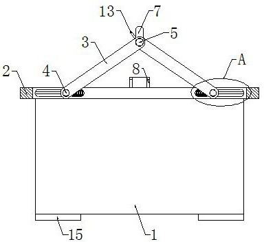
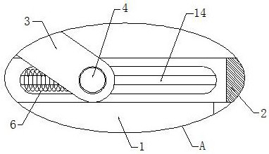
[0023] Example 1 as Figure 1-2 As shown, this double-fed inverter with a mounting plate for easy hoisting includes the inverter body 1 and the mounting plate 2, the mounting plate 2 is fixed on the top of the inverter body 1, and the top of the mounting plate 2 is symmetrically opened Two limit openings, and two adjustment rods 3 are arranged in the two limit openings, and one end of each adjustment rod 3 is provided with a round block 4, and the front and rear side walls of the two limit openings are symmetrically opened. There are two bar-shaped grooves matched with the round block 4, and a first spring 6 is arranged in each bar-shaped groove, and the two ends of the first spring 6 are connected with the side wall of the bar-shaped groove and the side of the round block 4 respectively. The wall is fixedly connected, and the top of the mounting plate 2 is provided with a rotating shaft 5, and the two ends of the rotating shaft 5 are respectively connected to the other ends o...
Embodiment 2
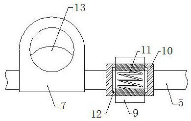
[0024] Embodiment 2 is on the basis of embodiment 1 such as figure 2 As shown, each of its limiting mechanisms includes two limiting blocks 9, a fixed block 10 and a second spring 11, the fixed block 10 is fixedly socketed with the rotating shaft 5, and the side wall of the fixed block 10 is provided with a position-limiting Block 9 matching limit hole, two limit blocks 9 and the second spring 11 are located in the limit hole, and the two ends of the second spring 11 are respectively fixedly connected with the side walls of the two limit blocks 9, both A limit block 9 and the suspension ring 7 are arranged parallel to each other.
Embodiment 3
[0025] Embodiment 3 is such as on the basis of embodiment 2 image 3 As shown, the two sidewalls of each of its limiting blocks 9 are fixedly connected with slide blocks 12, and the two sidewalls of each limiting hole are provided with chute matched with the sliding block 12, for the limiting blocks 9 position is limited.
PUM
 Abstract
Description
Claims
Application Information
 - R&D
- Intellectual Property
- Life Sciences
- Materials
- Tech Scout
- Unparalleled Data Quality
- Higher Quality Content
- 60% Fewer Hallucinations
Browse by: Latest US Patents, China's latest patents, Technical Efficacy Thesaurus, Application Domain, Technology Topic, Popular Technical Reports.
© 2025 PatSnap. All rights reserved.Legal|Privacy policy|Modern Slavery Act Transparency Statement|Sitemap|About US| Contact US: help@patsnap.com