Optoelectronic computing systems

A technology of light source and light input, applied in computing, optical computing equipment, optics, etc.

Pending Publication Date: 2021-02-26
ライテリジェンスインコーポレイテッド
View PDF1 Cites 13 Cited by
  • Summary
  • Abstract
  • Description
  • Claims
  • Application Information

AI Technical Summary

Problems solved by technology

The use of optical signals in computing platforms has been more restricted

Method used


Image

  • Optoelectronic computing systems
  • Optoelectronic computing systems
  • Optoelectronic computing systems

Examples


Embodiment 1

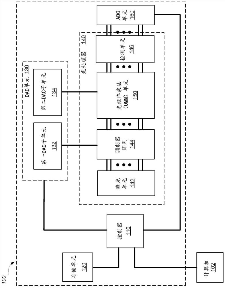
[0717] Embodiment 1: a kind of system, comprises:

[0718] a storage unit configured to store a data set and a plurality of neural network weights;

[0719] a digital-to-analog converter (DAC) unit configured to generate a plurality of modulator control signals, and generate a plurality of weight control signals;

[0720] Light processors, including:

[0721] a laser unit configured to generate a plurality of light outputs;

[0722]a plurality of optical modulators, coupled to the laser unit and the DAC unit, the plurality of optical modulators configured to generate an optical input vector by modulating a plurality of optical outputs generated by the laser unit based on a plurality of modulator control signals;

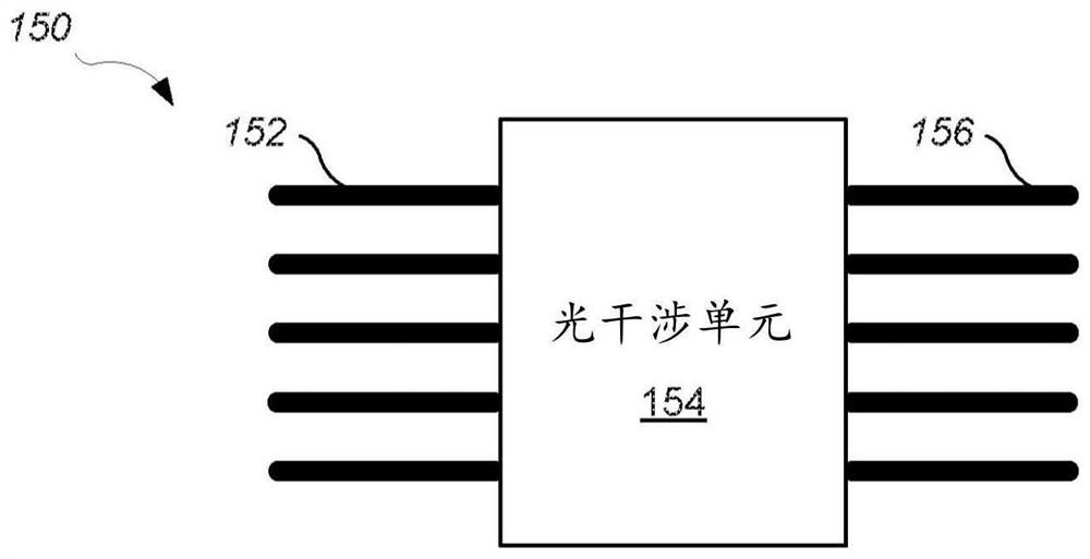
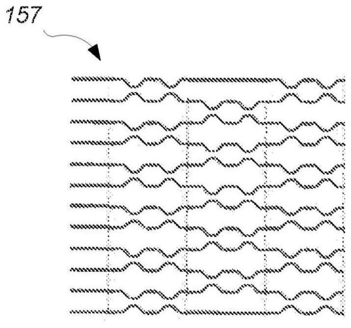
[0723] an optical matrix multiplication unit coupled to the plurality of optical modulators and the DAC unit, the optical matrix multiplication unit configured to convert an optical input vector into an optical output vector based on a plurality of weight control s...

Embodiment 2

[0730] Embodiment 2: The system of Embodiment 1, wherein the operations further comprise:

[0731] Obtain a first plurality of digital light outputs corresponding to the light output vector of the optical matrix multiplication unit from the ADC unit, and the first plurality of digital light outputs form a first digital output vector;

[0732] performing a non-linear transformation on the first digital output vector to produce a first transformed digital output vector; and

[0733] A first converted digital output vector is stored in a storage unit.

Embodiment 3

[0734] Embodiment 3: The system of Embodiment 2, wherein the system has a first cycle period defined as the step of storing the input data set and the first plurality of neural network weights in the storage unit is the same as storing the first plurality of neural network weights in the storage unit the elapsed time between the steps of converting the digital output vector, and

[0735] Wherein the first cycle period is less than or equal to 1 ns.


PUM


Abstract

Systems and methods that include: providing input information in an electronic format; converting at least a part of the electronic input information into an optical input vector; optically transforming the optical input vector into an optical output vector based on an optical matrix multiplication; converting the optical output vector into an electronic format; and electronically applying a non-linear transformation to the electronically converted optical output vector to provide output information in an electronic format. In some examples, a set of multiple input values are encoded on respective optical signals carried by optical waveguides. For each of at least two subsets of one or more optical signals, a corresponding set of one or more copying modules splits the subset of one or moreoptical signals into two or more copies of the optical signals. For each of at least two copies of a first subset of one or more optical signals, a corresponding multiplication module multiplies theone or more optical signals of the first subset by one or more matrix element values using optical amplitude modulation. For results of two or more of the multiplication modules, a summation module produces an electrical signal that represents a sum of the results of the two or more of the multiplication modules.

Description

[0001] Cross References to Related Applications [0002] This application claims U.S. Provisional Application 62 / 680,944, filed June 5, 2018, U.S. Provisional Application 62 / 744,706, filed October 12, 2018, U.S. Provisional Application 62 / 792,144, filed January 14, 2019 and priority to U.S. Provisional Application 62 / 820,562 filed March 19, 2019. The entire disclosure of said application is hereby incorporated by reference. technical field [0003] The present disclosure relates to an optoelectronic computing system. Background technique [0004] Neuromorphic computing is a method in the field of electronics that approximates the operation of the brain. A prominent approach to neuromorphic computing is the artificial neural network (ANN), which is a collection of artificial neurons that are interconnected in specific ways to process information in a manner similar to how the brain functions. ANNs have found use in a variety of applications, including artificial intelligen...

Claims


Application Information

Patent Timeline
Patent Type & Authority Applications(China)
IPC IPC(8): G06N3/04G06N3/067
CPCG06N3/063G06N3/08G06E1/045G06N3/045G06N3/0675G06N3/048G06N3/044G06N3/0475G02F1/00G02F1/225G02F3/024G06E3/005G06E3/006G06E3/008G06F17/14G06F17/16G06N3/047
Inventor 沈亦晨靖礼鲁门.丹高夫斯基谢鹏孟怀宇马修.高理卢正观罗纳德.加农莫里斯.斯坦曼吴建华阿拉什.侯赛因扎德赫
Owner ライテリジェンスインコーポレイテッド
Why Eureka
Try Eureka