
An automatic vibrating equipment for concrete in a building corner plate composite mold

A combined mold and concrete technology, which is applied in the direction of manufacturing tools and ceramic molding machines, can solve the problems of small thickness of building corner boards, low production of building corner boards, inconvenient vibration work of building corner boards, etc., to avoid column tilting, The effect of convenient vibrating work

Active Publication Date: 2022-05-06
江西华安建设集团有限公司
View PDF0 Cites 0 Cited by
  • Summary
  • Abstract
  • Description
  • Claims
  • Application Information

AI Technical Summary

Problems solved by technology

[0003] However, the existing vibrating equipment is usually used in the production of the building corner panels in the prior art, but the thickness of the building corner panels is not large, which causes the vibration work of the building corner panels to be very inconvenient, and the existing vibrating equipment is due to Inconvenient to use, resulting in low yields of building gussets

Method used


Image

  • An automatic vibrating equipment for concrete in a building corner plate composite mold
  • An automatic vibrating equipment for concrete in a building corner plate composite mold
  • An automatic vibrating equipment for concrete in a building corner plate composite mold

Examples


Embodiment

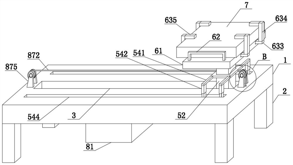
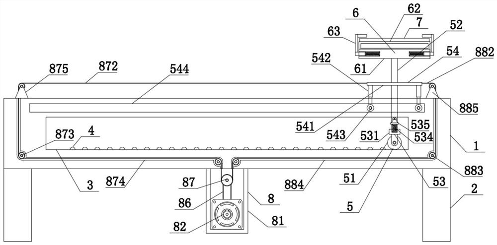
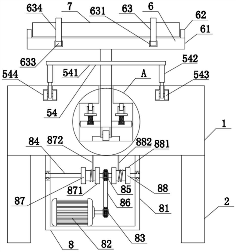
[0036] see also Figure 1-7 An automatic vibrating device for concrete in a building corner plate combined mold comprises a vibrating table 1, wherein the lower chamfers of the vibrating table 1 are fixedly connected with supporting legs 2; a first cavity 3 is arranged inside the vibrating table 1; a vibrating lug 4 is fixedly installed inside the first cavity 3; a vibrating mechanism 5 is movably connected inside the first cavity 3; a fixing rod at the upper end of the vibrating mechanism 5 is connected with a fixing mechanism 6; and a combined mold body 7 is movably connected inside the fixing mechanism 6.

[0037] The vibrating mechanism 5 includes a first roller 51, an upright post 52, a limiting assembly 53 and a positioning assembly 54, wherein the first roller 51 is rotatably connected to the inside of the first cavity 3, and the upright post 52 is fixedly installed at the upper end of the first roller 51, and the upper end of the upright post 52 penetrates through the vibra...


PUM


Abstract

The invention discloses an automatic vibrating equipment for concrete in a building angle plate composite mold, which includes a vibrating table, the lower chamfers of the vibrating table are fixedly connected with outriggers, and the inside of the vibrating table is provided with a second A cavity, the inside of the first cavity is fixed with a vibration bump, and the inside of the first cavity is movably connected with a vibration mechanism; the fixing mechanism can place and fix the combined mold body, and the transmission mechanism drives the vibration mechanism to move , the first roller is in contact with the vibration bump during the moving process, and the first roller moves up and down through the setting of the vibration bump, and the first roller quickly rebounds through the limit assembly, so as to achieve the effect of vibration, and Vibration is transmitted to the fixing mechanism through the column, so that the combined mold body that is movably connected inside the fixing mechanism vibrates, thereby facilitating the vibrating work of the concrete inside the mold, so that the present invention not only facilitates the vibrating work of the mold, but also enables rapid and batch production .

Description

Technical field [0001] The invention relates to the field of prefabricated buildings, in particular to an automatic vibrating device for concrete in a building corner plate combined mold. technical background [0002] Concrete vibratory machines are machines and tools for tamping concrete by using the vibration of mechanical parts, including plug-in, attached, flat-plate and vibrating table for vibrating precast concrete components, etc. They are widely used in construction sites and concrete products factories, such as rural road construction. When pouring concrete components with concrete mixer, air bubbles must be removed, tamping must be carried out, so that concrete can be tightly combined, and honeycomb pits of concrete can be eliminated to improve its strength. To ensure the quality of concrete components, building corner plates are widely used in the actual construction process. Using combined mold to produce building corner plates greatly increases the production quantit...

Claims


Application Information

Patent Timeline
Patent Type & Authority Patents(China)
IPC IPC(8): B28B1/087B28B1/04
CPCB28B1/0873B28B1/045B28B2001/0876
Inventor 郭卫洪文彬
Owner 江西华安建设集团有限公司
Learn More