fan frame

A fan frame and frame technology, which is applied in the direction of instruments, liquid fuel engines, machines/engines, etc., can solve problems such as fan vibration, electronic equipment temperature rise, and fans are prone to noise, so as to achieve stable operation, reduce noise, and avoid The effect of resonance

Active Publication Date: 2021-06-22
DELTA ELECTRONICS INC
View PDF6 Cites 0 Cited by
  • Summary
  • Abstract
  • Description
  • Claims
  • Application Information

AI Technical Summary

Problems solved by technology

[0002] With the continuous improvement of the performance of electronic devices, the current electronic devices will generate a lot of waste heat during operation. If the heat cannot be taken away from the electronic devices immediately, the temperature of the electronic devices will increase, causing damage to internal components and reducing the efficiency of the electronic devices. and service life
Fans are widely used in heat dissipation devices for electronic devices. In order to dissociate a large amount of waste heat from electronic devices, under the premise of fans of the same size, the speed of the fans must be increased to increase the heat dissipation efficiency of the fans. However, the known fan products Usually a single plastic material is used as the structure of the fan frame. As the speed increases, the fan is prone to vibration problems, and the fan made of a single material will cause the fan frame to generate a resonance effect, which will cause the vibration source to be concentrated and amplified, which will cause the fan to be prone to vibration. Noisy, or even unstable operation occurs

Method used


Image

  • fan frame
  • fan frame
  • fan frame

Examples


Embodiment Construction

[0060] The preferred embodiments of the fan frame according to the present invention will be described below with reference to the relevant drawings, wherein the same elements will be described with the same reference symbols.

[0061] The fan frame of the invention can make the fan run stably while reducing the noise, thereby prolonging the service life of the fan and maintaining the operating efficiency of the fan. The structure and features of the fan frame of the present invention will be described below with examples.

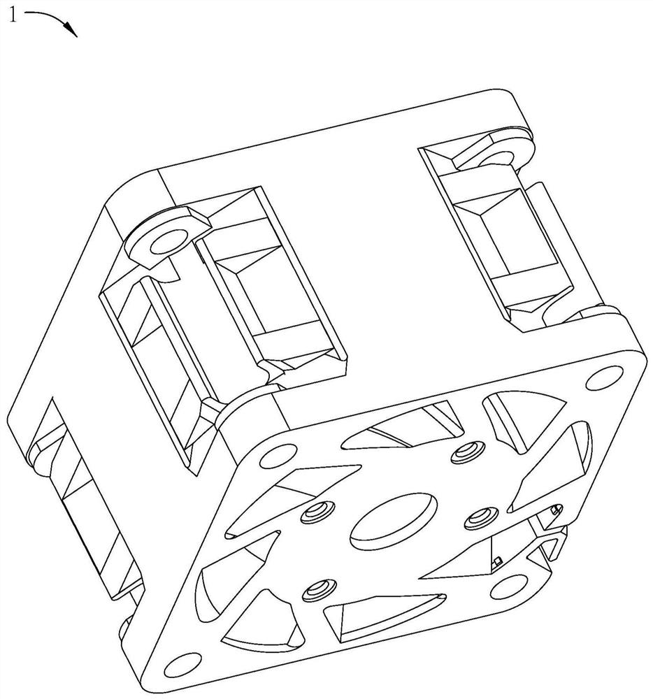
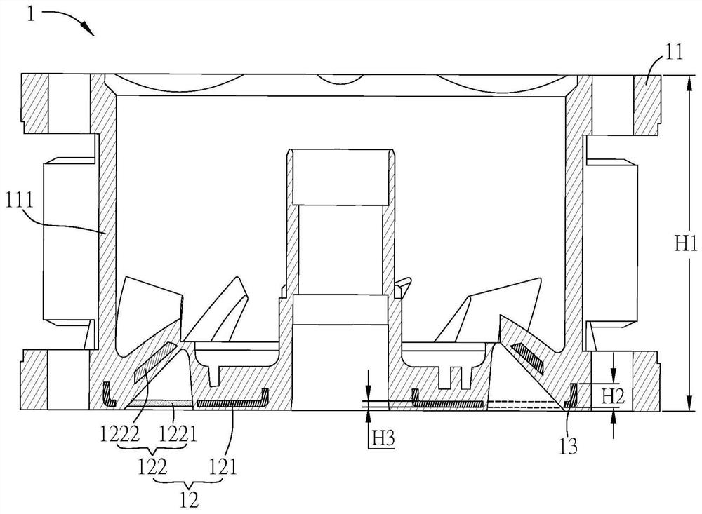
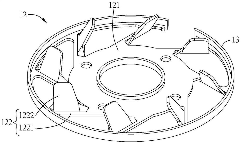
[0062] Please refer to Figure 1A to Figure 1C , which is a schematic diagram of a preferred embodiment of the fan frame 1 of the present invention.

[0063] The fan frame 1 includes a frame body 11 and a metal base 12 . The metal base 12 may be a structure assembled with the frame body 11 , or may be a structure covered and formed in the frame body 11 .

[0064] The frame body 11 includes a frame wall 111 . The metal base 12 includes a central portion...


PUM


Abstract

The invention discloses a fan frame, which comprises a frame body and a metal base. The frame body includes a frame wall, and the metal base includes a central part and a plurality of stator blades. The plurality of vanes extend radially from the center and are connected to the frame wall, and the material of the frame body is different from that of the vanes. The invention also discloses a fan frame, which includes a base and a frame body. The frame body includes a metal frame wall and a plurality of stationary vanes. The plurality of stationary vanes extend radially inward from the metal frame wall and are connected to the base, and the material of the frame body is different from that of the stationary vanes. The invention also discloses a fan frame, which includes a frame body, a base and a plurality of stator blades. The frame body includes frame walls. One end of the plurality of stationary vanes is connected to the base, and the other end is connected to the frame wall, wherein at least a part of the plurality of stationary vanes is made of metal, and the material of the frame body is different from that of the stationary vanes.

Description

technical field [0001] The invention relates to a fan frame, in particular to a fan frame composed of metal and plastic. Background technique [0002] With the continuous improvement of the performance of electronic devices, the current electronic devices will generate a lot of waste heat during operation. If the heat cannot be taken away from the electronic devices immediately, the temperature of the electronic devices will increase, causing damage to internal components and reducing the efficiency of the electronic devices. and service life. Fans are widely used in heat dissipation devices for electronic devices. In order to dissociate a large amount of waste heat from electronic devices, under the premise of fans of the same size, the speed of the fans must be increased to increase the heat dissipation efficiency of the fans. However, the known fan products Usually a single plastic material is used as the structure of the fan frame. As the speed increases, the fan is pro...

Claims


Application Information

Patent Timeline
Patent Type & Authority Patents(China)
IPC IPC(8): F04D29/52F04D29/66F04D29/02F04D25/08G06F1/20
CPCF04D25/08F04D29/023F04D29/522F04D29/668G06F1/20
Inventor 谢明凯吴志辉刘耿华
Owner DELTA ELECTRONICS INC
Why Eureka
Try Eureka