Detection device and detection method for PCB
A technology for a PCB circuit board and a detection device, which is applied in the field of PCB circuit board detection equipment, can solve the problems of many detection steps, troubled detection personnel, and complicated operation.
- Summary
- Abstract
- Description
- Claims
- Application Information
AI Technical Summary
Problems solved by technology
Method used
Image
Examples
Embodiment 1
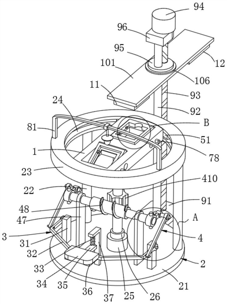
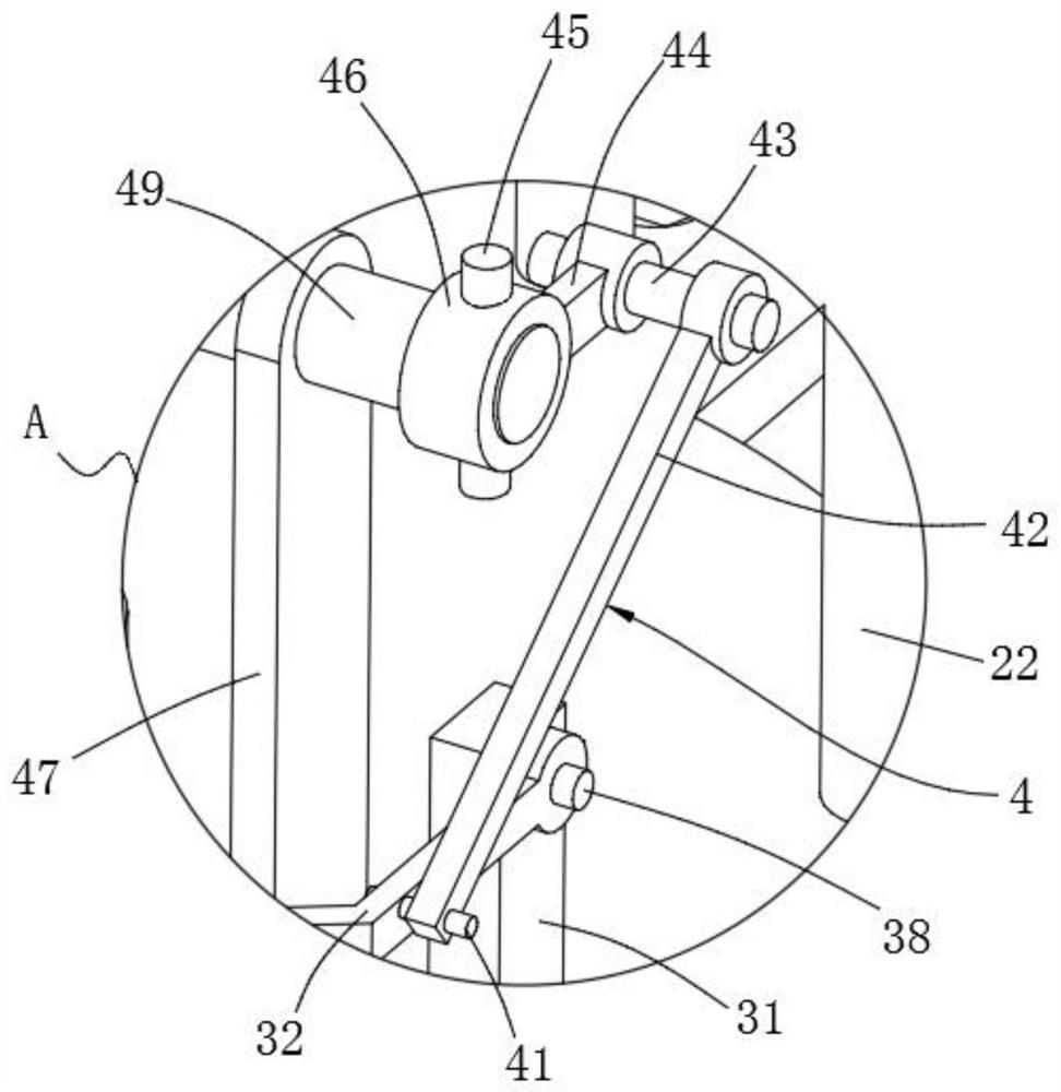
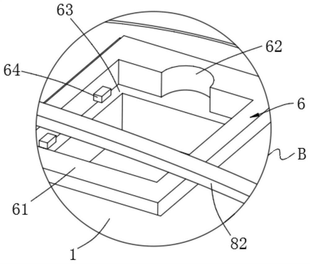
[0046] Example 1, please refer to Figure 1-8 , this embodiment provides a technical solution: a detection device for a PCB circuit board, including a rotating board 1, a supporting unit 2, a rotating power unit 3, a rotating transmission unit 4, a sliding unit 5, a circuit board carrying unit 6, and a lifting unit 9 and detection alternate unit 10;
[0047] The support unit 2 includes a chassis 21, a pillar 22, a support ring 23, an annular groove 24, a shaft seat 25 and a bearing 26. The rear surface of the chassis 21 is connected to the support ring 23 through the pillar 22, and the inner side of the support ring 23 is provided with a ring groove 24, and the center of the surface of the chassis 21 is fixed with a shaft seat 25, and a bearing 26 is installed on the shaft seat 25;
[0048] The two ends of the rotating plate 1 are slidingly connected to the annular groove 24 through the sliding unit 5, the bottom of the rotating plate 1 is connected with the rotating transmis...
Embodiment 2
[0069] Example 2, please refer to Figure 4 and 8 , the present embodiment provides a technical solution: a detection device for a PCB circuit board. Groove 72, overturn shaft fixing bar 73, overturn shaft seat 74, overturn control spring 75, vertical bar 76, sliding column 77, button 78, chuck 79 and snap-in groove 710, the both sides middle part of bearing frame 61 is respectively fixed with overturn The shaft 71, the side of the detection channel of the rotary plate 1 is provided with a rotation channel 72 corresponding to the rotation axis 71, and the rotation shaft 74 is connected to the rotation shaft 71 on the rotation plate 1, and the rotation shaft seat 74 is fixed on the rotation channel 72 by the rotation shaft fixing rod 73 Inside, the flip shaft 71 is fixed with a chuck 79 at one end away from the bearing frame 61, and the side of the chuck 79 close to the bearing frame 61 is equiangularly provided with a clamping groove 710, and one side of the rotating through ...
Embodiment 3
[0071] Embodiment three, please refer to Figure 8 , this embodiment provides a technical solution: a detection device for a PCB circuit board. The difference between this embodiment and the above embodiments is that it also includes a lighting unit 8. Slide bar 82, slide sleeve 83, gooseneck 84, lampshade 85 and lighting lamp 86, the front side of support ring 23 is provided with two left and right corresponding lighting poles 81, and the two ends of arc-shaped slide bar 82 are fixedly connected two The top of the lighting pole 81 is slidably connected with a sliding sleeve 83 on the arc-shaped sliding rod 82 , and the bottom of the sliding sleeve 83 is connected with a lampshade 85 through a gooseneck 84 , and a lighting lamp 86 is installed at the bottom of the lampshade 85 .
[0072] The lateral position of the lighting lamp 86 can be changed by sliding the sliding sleeve 83 on the arc-shaped sliding rod 82, and the lighting lamp 86 can be changed to any angle through the ...
PUM
 Abstract
Description
Claims
Application Information
 - R&D
- Intellectual Property
- Life Sciences
- Materials
- Tech Scout
- Unparalleled Data Quality
- Higher Quality Content
- 60% Fewer Hallucinations
Browse by: Latest US Patents, China's latest patents, Technical Efficacy Thesaurus, Application Domain, Technology Topic, Popular Technical Reports.
© 2025 PatSnap. All rights reserved.Legal|Privacy policy|Modern Slavery Act Transparency Statement|Sitemap|About US| Contact US: help@patsnap.com


