
Vertical winding unit for punched nickel-plated steel strip in the annealed state

A technology of winding device and nickel-plated steel, which is applied in the field of winding device, can solve problems such as edge warping, large misalignment range, and large process fluctuation, and achieve the effect of neat end surface of steel strip, simple structure and convenient operation

Active Publication Date: 2019-07-30
CHANGDE LYRUN MATERIAL
View PDF5 Cites 0 Cited by
  • Summary
  • Abstract
  • Description
  • Claims
  • Application Information

AI Technical Summary

Problems solved by technology

[0002] At present, the equipment used for winding the annealed punched nickel-plated steel strip is generally a horizontal winding machine. Because the thickness of the edge coating of the annealed punched nickel-plated steel strip is generally three times higher than the thickness of the middle coating, the winding process Medium-annealed punched nickel-plated steel strip needs misalignment control; if misalignment control is not performed, the edge of the product will be squeezed due to the high thickness of the coating, and deformation such as warping will occur; at the same time, as the winding progresses, the The tension at the barrel increases gradually, and the product is severely squeezed and deformed
In order to avoid edge deformation, the existing technology generally needs to control the misalignment range above 3mm, but in the post-processing process, when passing through automatic processing equipment, due to the large misalignment range and large process fluctuations, it cannot be processed normally

Method used


Image

  • Vertical winding unit for punched nickel-plated steel strip in the annealed state

Examples


Embodiment Construction

[0012] Specific embodiments of the present invention will be described in detail below in conjunction with the accompanying drawings. It should be understood that the specific embodiments described here are only used to illustrate and explain the present invention, and are not intended to limit the present invention.

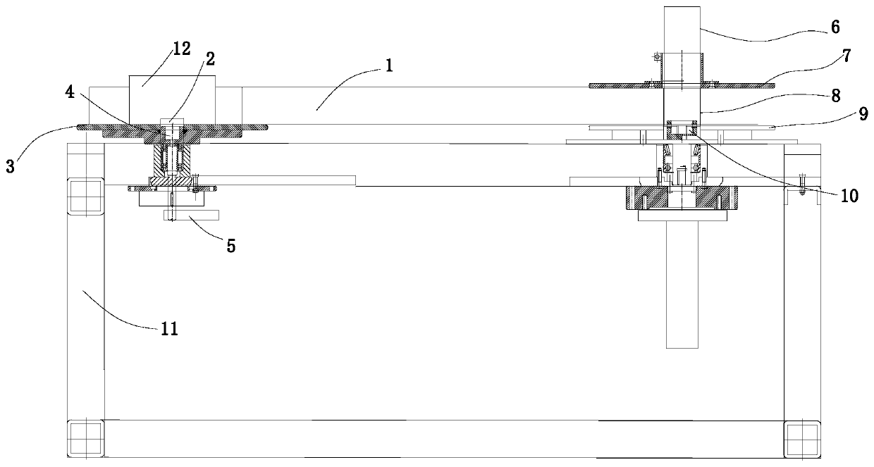
[0013] refer to figure 1 , in the preferred mode of the present invention, the present invention provides a kind of vertical winding device that is used for annealed punching nickel-plated steel strip, and this device comprises frame 11 and is arranged on frame 11 unwinding device and take-up volume device. Wherein, the unwinding device includes an unwinding tray 3, the unwinding tray 3 is used to fix the unwinding core barrel 12, and the unwinding core barrel 12 is used to fix the annealed steel strip product, and the unwinding device also includes a The taper tension controller 5 at the bottom of the volume tray 3; the winding device includes a winding tray ...


PUM

PropertyMeasurementUnit
hardnessaaaaaaaaaa
thicknessaaaaaaaaaa

Abstract

The invention provides a vertical winding device for an annealing state punching nickel-plated steel strip. The vertical winding device comprises a machine frame, a winding device and an unwinding device, wherein the winding device is arranged on the machine frame. The winding device comprises an unwinding tray and a taper tension controller, wherein the unwinding tray is used for fixing an unwinding spool, and the taper tension controller is arranged at the bottom of the unwinding tray. The winding device comprises a winding tray, a winding shaft, a winding driving piece and a winding roll core cylinder, wherein the axis of the winding shaft is in a vertical state and can be fixed on the winding tray, the winding driving piece is in driving connection with the winding shaft, and the winding roll core cylinder sleeves the winding shaft. The unwinding tray and the winding tray are located in the same horizontal plane. The unwinding tray and the winding tray are arranged in a horizontalline, and the taper tension controller is arranged on the unwinding device, so that constant-tension winding can be achieved in the winding process, staggered-layer winding does not need to be carriedout, and the end face of the rolled steel strip is neat; and the device is simple in structure and convenient to operate.

Description

technical field [0001] The invention relates to a winding device, in particular to a vertical winding device for annealed punched nickel-plated steel strip. Background technique [0002] At present, the equipment used for winding the annealed punched nickel-plated steel strip is generally a horizontal winding machine. Because the thickness of the edge coating of the annealed punched nickel-plated steel strip is generally three times higher than the thickness of the middle coating, the winding process Medium-annealed punched nickel-plated steel strip needs misalignment control; if misalignment control is not performed, the edge of the product will be squeezed due to the high thickness of the coating, and deformation such as warping will occur; at the same time, as the winding progresses, the The tension at the barrel gradually increases, and the product is severely squeezed and deformed. In order to avoid edge deformation, the existing technology generally needs to control t...

Claims


Application Information

Patent Timeline
Patent Type & Authority Patents(China)
IPC IPC(8): B21C47/02
CPCB21C47/02
Inventor 肖腾彬肖进春钟发平候群胡越高夏健康彭朋飞
Owner CHANGDE LYRUN MATERIAL
Learn More