
A coupling device for light emitting and receiving components

A coupling device, transmitting and receiving technology, applied in the field of coupling devices for optical transmitting and receiving components, can solve the problems of few adjustment directions, difficult operation, low adjustment accuracy, etc., achieve strong practicability, convenient coupling operation, and improve coupling efficiency Effect

Active Publication Date: 2022-02-11
四川九州光电子技术有限公司
View PDF8 Cites 0 Cited by
  • Summary
  • Abstract
  • Description
  • Claims
  • Application Information

AI Technical Summary

Problems solved by technology

[0004] However, the transmission speed of the existing optical transmitter module and light receiving assembly is low, and the optical transmitter module and light receiving assembly with low transmission speed are easy to couple because of their simple structure when coupling, but for the structure is more complex and There are multiple TO-CAN optical transmitter modules with faster transmission rates and optical receiving components. When coupling with conventional coupling devices, there are fewer adjustment directions and lower adjustment accuracy, resulting in the existence of multiple TO-CAN The coupling of the optical transmitter module and the optical receiving component, while using the existing coupling device, has low production efficiency, low yield, and difficult operation, which seriously affects the high transmission speed optical transmitter module and optical receiving component. Productivity of components

Method used


Image

  • A coupling device for light emitting and receiving components
  • A coupling device for light emitting and receiving components
  • A coupling device for light emitting and receiving components

Examples


Embodiment Construction

[0055] In order to make the purpose, technical solutions and advantages of the embodiments of the present invention clearer, the technical solutions in the embodiments of the present invention will be clearly and completely described below in conjunction with the drawings in the embodiments of the present invention. Obviously, the described embodiments It is a part of embodiments of the present invention, but not all embodiments. The components of the embodiments of the invention generally described and illustrated in the figures herein may be arranged and designed in a variety of different configurations.

[0056] Accordingly, the following detailed description of the embodiments of the invention provided in the accompanying drawings is not intended to limit the scope of the claimed invention, but merely represents selected embodiments of the invention. Based on the embodiments of the present invention, all other embodiments obtained by persons of ordinary skill in the art wi...


PUM


Abstract

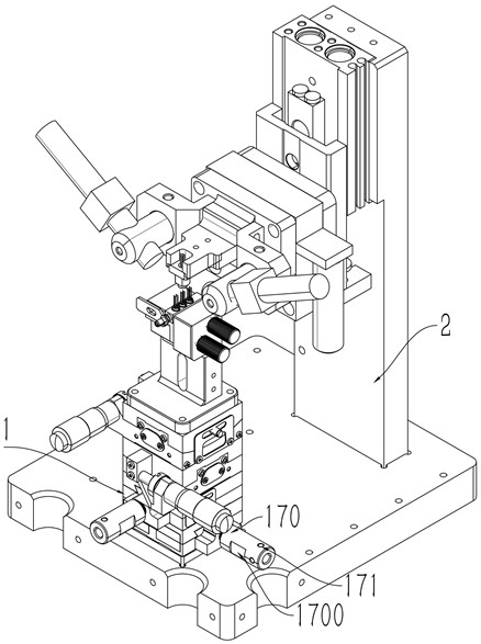
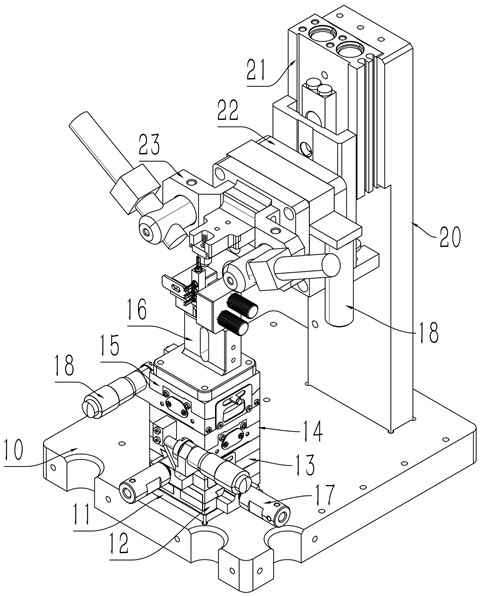
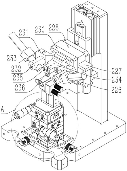
A coupling device for a light emitting and receiving component, including an adjustment component and a fixed connection component, wherein the fixed connection component includes a vertical plate extending upwards on one side of the bottom plate, and a lifting member is arranged on the inner side of the top of the vertical plate, and the movement of the lifting component The end is connected with a rotating member, the rotating drive assembly is arranged on the rotating member, and the rotating member is provided with a curing head. The present invention performs the coupling operation of multiple TO-CAN optical transmitter modules and optical receiving components, and can perform adjustments in multiple directions during operation, and can perform rotations in multiple directions at the same time, which significantly improves the overall light emission of this type. The coupling efficiency, coupling yield and production efficiency of the optical transmitter module and the light receiving component can be clamped vertically or flat on the shell of the light transmitter module and the light receiving component, so as to facilitate the coupling of the light transmitter module and the light receiving component Coupling operation has strong practicability.

Description

technical field [0001] The invention relates to the related technical field of production equipment of light emitting and receiving components, in particular to a coupling device for light transmitting and receiving components. Background technique [0002] The main component of the TOSA Transmitting Optical Sub-Assembly optical transmitter module, which mainly completes the conversion of electrical signals to optical signals. Among them, the light source semiconductor light-emitting diode or laser diode is the core, LD chip, monitoring photodiode MD and other components are packaged in a compact structure TO coaxial package or butterfly package. [0003] The main function of ROSA Receiving Optical Sub-Assembly is to convert optical signals into electronic signals through the photoelectric effect. Common photodetectors in optical communications are PIN photodiodes and avalanche photodiodes (APDs). [0004] However, the transmission speed of the existing optical transmitter...

Claims


Application Information

Patent Timeline
Patent Type & Authority Patents(China)
IPC IPC(8): G02B6/42
CPCG02B6/4228
Inventor 李旭项刚杜江李中德赵涵罗良润袁娟
Owner 四川九州光电子技术有限公司
Learn More