
Novel charging connector

A charging connector and connector technology, which is applied in the direction of connection, charging station, electric vehicle charging technology, etc., can solve the problems of high design requirements, low mass assembly production efficiency, difficult terminal disassembly process, etc., and achieve high production efficiency and fast Blind assembly and disassembly, easy maintenance

Active Publication Date: 2021-03-02
CHINA AVIATION OPTICAL-ELECTRICAL TECH CO LTD
View PDF6 Cites 2 Cited by
  • Summary
  • Abstract
  • Description
  • Claims
  • Application Information

AI Technical Summary

Problems solved by technology

[0003] In order to solve the need to carry parts such as pressure plates and end caps during the connection process of existing connector terminals and wires, resulting in high design requirements for terminal connection equipment, protection of the carried parts, complicated connector assembly process, low mass assembly production efficiency and terminal disassembly The technical problem of difficult process, the present invention proposes a new charging connector

Method used


Image

  • Novel charging connector
  • Novel charging connector
  • Novel charging connector

Examples


specific Embodiment 2

[0032] The second specific embodiment is as follows:

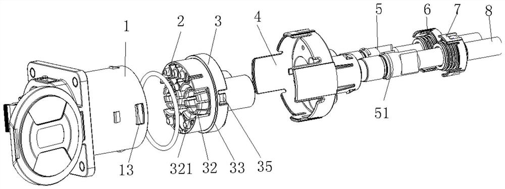
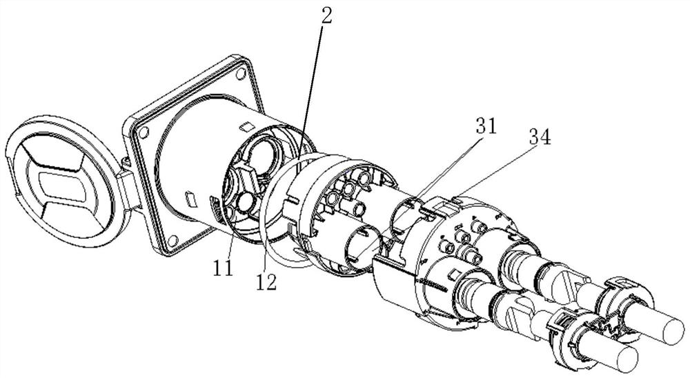
[0033] On the basis of the specific embodiment 1, as an alternative, the pressure plate 3 can also be limited in the accommodating cavity 11 by the tail cover 4. At this time, it is not necessary to provide the snap structure, and the tail cover can be removed from the connector housing. After being disassembled, the pressing plate and the terminal part can be directly taken out, and then the elastic tooth piece 321 of the elastic tooth structure hole can be deformed by the tooling, so that the terminal part can be withdrawn to the rear end, and the whole terminal part can be completed.

[0034] Further, the charging connector of the present invention is further provided with a temperature monitoring mechanism. The temperature monitoring mechanism includes a accommodating groove 101, a temperature monitoring device 102, a sealing member 103 and a monitoring device fixing member 104. The accommodating groove 101 is opened on...


PUM


Abstract

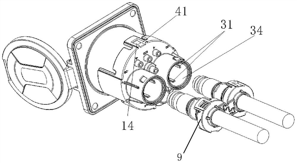
A novel charging connector comprises a connector shell and a tail cover installed at the rear end of the connector shell, a containing cavity is formed in the connector shell, a pressing plate is installed in the containing cavity, and a penetrating hole for a terminal part to penetrate through is formed in the pressing plate in the axial direction. The penetrating hole comprises an elastic tooth-shaped structure hole formed in the front end of the pressing plate and a guide hole formed in the rear end of the pressing plate and communicated with the elastic tooth-shaped structure hole, the guide hole penetrates out of the rear end of the tail cover, and a boss is arranged on the terminal part. During installation, the terminal part is inserted into the penetrating hole from the guide holeand reaches the fixing position after moving to the boss and passing through the elastic tooth-shaped structure hole, and at the moment, the boss is limited between the front end face of the elastic tooth-shaped structure hole and a stop part arranged in the connector shell. By means of the technical scheme, the terminal part is installed from the tail of the connector independently, the requirement for a wire and terminal connecting device is not high, rapid blind installation and detachment of the terminal part can be achieved, the production efficiency is high, and the terminal part is suitable for mass production.

Description

technical field [0001] The invention belongs to the technical field of connectors, and particularly relates to a novel charging connector. Background technique [0002] The terminal of the new energy vehicle charging connector (charging socket or charging plug) is fixed inside the charging connector. Generally, the terminal is connected to the wire with parts such as a pressure plate, a sealing ring and a fixed cover at the end of the connector. The terminal and the wire are generally crimped, ultrasonic It should be connected by welding and other methods, and the connecting equipment should avoid the bulky and complex parts carried by the terminal, such as the pressure plate, the sealing ring and the fixed cover at the end of the connector. This puts forward great space and structural requirements for the terminal connecting equipment. When connecting, it is necessary to protect the carried parts. After the terminal is connected, the terminal is first assembled inside the ...

Claims


Application Information

Patent Timeline
Patent Type & Authority Applications(China)
IPC IPC(8): H01R13/627H01R13/629H01R13/66B60L53/16
CPCH01R13/627H01R13/629H01R13/66B60L53/16Y02T90/16
Inventor 鲍红力范利海王伟赵园园
Owner CHINA AVIATION OPTICAL-ELECTRICAL TECH CO LTD
Learn More