
Torsion Bar Piezo Actuator

A technology of piezoelectric actuation and torsion bar, which is applied to the device and coating of the surface coating liquid, which can solve the problems of pre-force variation, difficulty for users, and setting of operating parameters, so as to achieve accurate control of output and optimal operation Optimized effect

Active Publication Date: 2022-08-02
ADVANCED JET AUTOMATION CO LTD
View PDF0 Cites 0 Cited by
  • Summary
  • Abstract
  • Description
  • Claims
  • Application Information

AI Technical Summary

Problems solved by technology

However, factors such as spring relaxation and piezoelectric actuator aging will lead to changes in the pre-force, which in turn will affect the accuracy of the glue output
In addition, due to the unknown state of the pre-force change, it is also difficult for users to set relevant operating parameters according to the characteristics of the adhesive material

Method used


Image

  • Torsion Bar Piezo Actuator
  • Torsion Bar Piezo Actuator
  • Torsion Bar Piezo Actuator

Examples


Embodiment Construction

[0045] The following will disclose various embodiments of the present application with drawings, and for the sake of clarity, many practical details will be described together in the following description. It should be understood, however, that these practical details should not be used to limit the present case. That is, in some embodiments of the present case, these practical details are unnecessary. In addition, in order to simplify the drawings, some conventionally used structures and elements will be shown in a simple and schematic manner in the drawings.

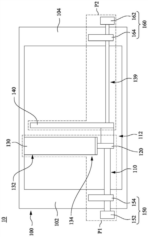
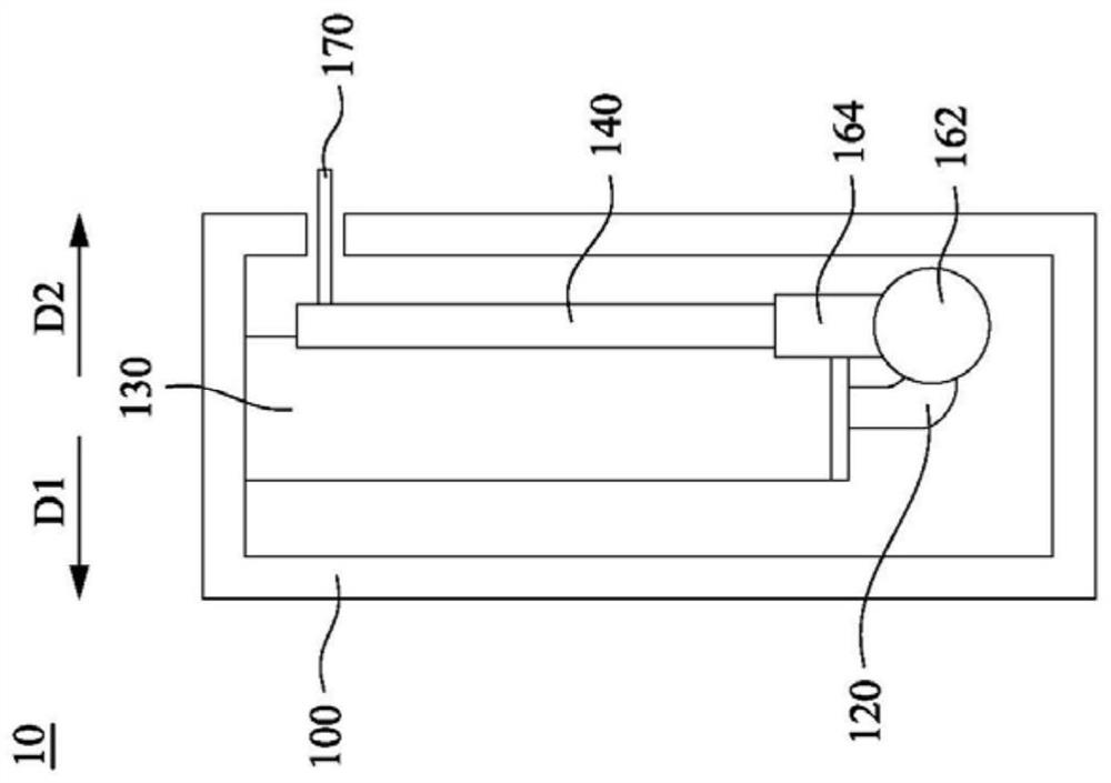
[0046] Please refer to figure 1, which is a schematic front view of the piezoelectric actuator 10 according to some embodiments of the present application. In some embodiments, the piezoelectric actuating device 10 includes a housing 100, a first torsion bar 110, a first force applying unit 120, a piezoelectric unit 130, a second torsion bar 139, a second force applying unit 140, a first force applying unit 130, a T...


PUM


Abstract

A torsion bar type piezoelectric actuating device includes a housing, a first torsion bar, a second torsion bar, a connecting shaft, a first force applying unit, a piezoelectric unit and a second force applying unit. The first and second torsion bars are respectively penetrated through the casing. The first and second torsion bars can be connected in series with shafts, or connected by rods. The first force applying unit is fixed on the first torsion bar. The piezoelectric unit has two ends, which are respectively abutted against the casing and the first force applying unit. The second force applying unit is fixed to the second torsion bar, and is arranged spaced apart from the first force applying unit. When a voltage is applied to the piezoelectric unit to expand or contract, the piezoelectric unit rotates the first and second torsion bars through the first force applying unit, thereby driving the second force applying unit to reciprocate. The piezoelectric actuator of the present case can observe and adjust the pre-force applied to the device through the pre-force adjustment mechanism, so that the device can accurately control the output and optimize the operation.

Description

technical field [0001] This case is about a piezoelectric actuator, especially a piezoelectric actuator used in dispensing equipment. Background technique [0002] The conventional glue dispensing equipment utilizes a mechanical glue dispensing valve to control the output of the glue material. The mechanical dispensing valve extrudes and sends out the rubber material by the repeated action of air pressure and spring. However, factors such as spring relaxation and piezoelectric actuator aging will lead to pre-force changes, which in turn affect the accuracy of the glue output. In addition, since the state of the pre-force change is unknown, it is also difficult for the user to set relevant operating parameters according to the characteristics of the rubber material. Therefore, at present, the industry is eager to invest resources to develop an actuating device that can solve the above problems. SUMMARY OF THE INVENTION [0003] According to one or more embodiments of the...

Claims


Application Information

Patent Timeline
Patent Type & Authority Patents(China)
IPC IPC(8): B05C5/02B05C11/10
CPCB05C5/0225B05C11/10B05C11/1026
Inventor 陈律名周元昉吴佳霖
Owner ADVANCED JET AUTOMATION CO LTD
Learn More