
Keel assembly and wall surface assembly

A keel and component technology, which is applied in the field of prefabricated decoration, can solve the problems of keel bending, reducing the flatness of the wall, and the distance between the wall panel and the structural wall cannot be adjusted, and achieves the effect of avoiding swing and improving stability.

Active Publication Date: 2021-03-05
TIANJIN DAYIN BUILDING MATERIAL CO LTD
View PDF18 Cites 4 Cited by
  • Summary
  • Abstract
  • Description
  • Claims
  • Application Information

AI Technical Summary

Problems solved by technology

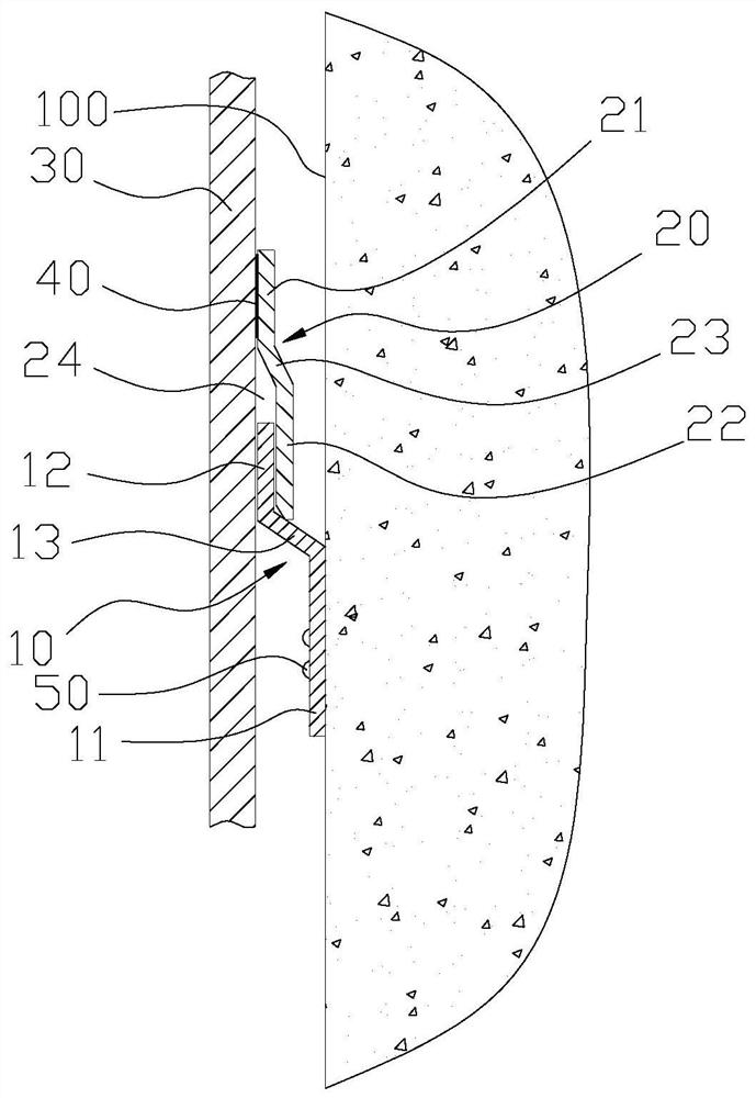
[0004] 1. Because the fixing strip of the keel needs to be attached to the structural wall, the keel can be fixed, which leads to the inability to adjust the distance between the insert and the structural wall, which leads to, on the one hand: the wall panel and the structural wall The distance between them cannot be adjusted; on the other hand: if the structural wall is uneven in the extension direction of the keel, this will cause the keel to bend due to the need to attach to the structural wall, which in turn leads to the following unfavorable results: 1). Reduce the flatness of the wall surface spliced ​​by parallel wallboards; 2) It may cause dislocation in the thickness direction between adjacent wallboards; 3) The cutting strips are bent in the extension direction of the keel to increase the cutting strips Difficulty of inserting the slot
[0005] 2. If figure 1 As mentioned above, the wallboard is only in contact with the cutting strips, resulting in an unstable installation state of the wallboard, and the wallboard is prone to swing in the thickness direction of the wallboard (that is, in the direction close to or away from the structural wallboard)

Method used


Image

  • Keel assembly and wall surface assembly
  • Keel assembly and wall surface assembly
  • Keel assembly and wall surface assembly

Examples


Embodiment Construction

[0054] In order to make the purpose, technical solutions and advantages of the embodiments of the present invention more clear, the technical solutions of the embodiments of the present invention will be clearly and completely described below in conjunction with the drawings of the embodiments of the present invention. Apparently, the described embodiments are some, not all, embodiments of the present invention. Based on the described embodiments of the present invention, all other embodiments obtained by persons of ordinary skill in the art without creative efforts shall fall within the protection scope of the present invention.

[0055] Unless otherwise defined, the technical terms or scientific terms used in the present invention shall have the usual meanings understood by those skilled in the art to which the present invention belongs. "First", "second" and similar words used in the present invention do not indicate any order, quantity or importance, but are only used to dis...


PUM


Abstract

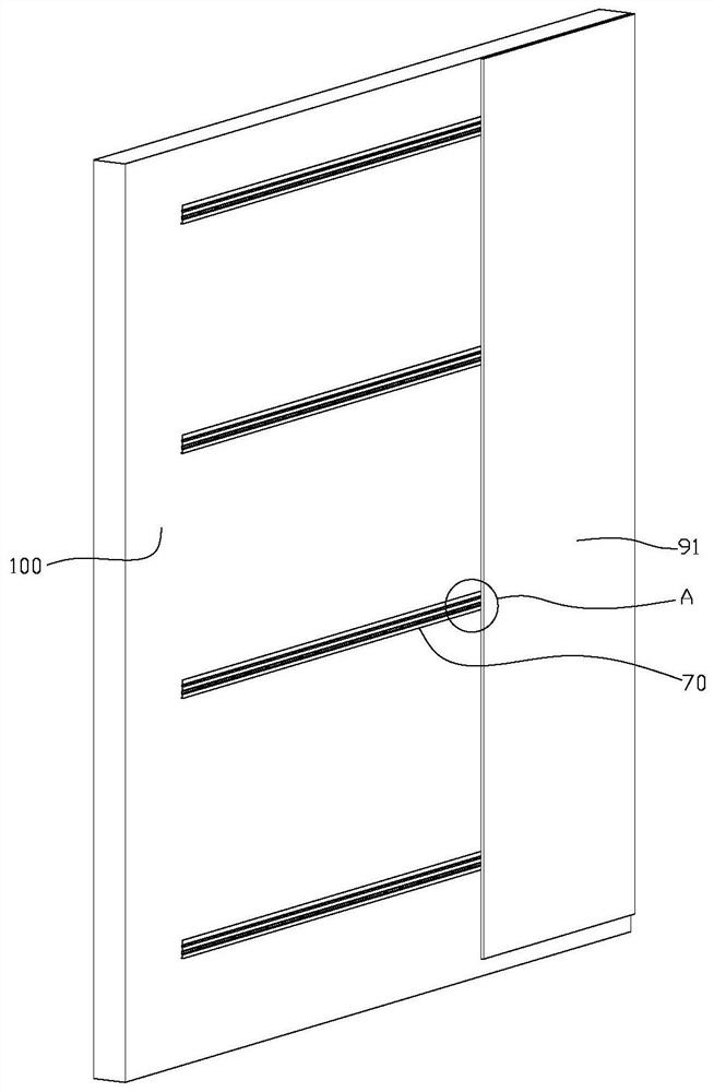
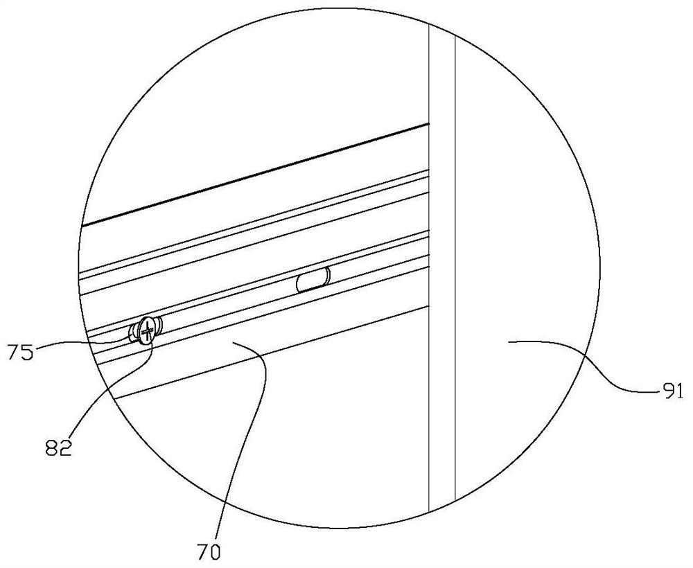
The invention discloses a keel assembly and a wall surface assembly. The keel assembly comprises a lath-shaped keel and a plurality of groups of fastening parts. The plurality of groups of fastening parts are arranged in the extending direction of keels; each fastening part at least comprises an adjusting part, the adjusting parts comprise screw rods used for extending into a structural wall and cushion blocks formed at the tails of the screw rods, and the keels are fixed to the cushion blocks, so that inserting strips are formed on the upper sides of the keels. When the interval between a wallboard and the structural wall needs to be adjusted, the screw rod of each adjusting part is screwed, then the depth of the screw rods extending into the structural wall is changed, the distance between the outer side faces of the cushion blocks and the structural wall can be adjusted, and then the interval between the keels and the structural wall and the interval between the inserting strips onthe upper sides of the keels and the structural wall can be adjusted. The inserting strips are inserted into inserting seams formed by hanging pieces, so that the interval between the wallboard and the structural wall is adjusted certainly.

Description

technical field [0001] The invention relates to the technical field of prefabricated decoration, in particular to a keel component and a wall component. Background technique [0002] The Chinese utility model patent with the patent number 201921170327.8 (this patent is the applicant's prior application) discloses a keel, a pendant and a wall component. Such as figure 1 As shown, the keel 10 in the technical solution claimed in this patent includes a fixing strip 11 and an inserting strip 12, and the hanger 20 therein includes a holding plate 22 and a fixing plate 21; Firmware (screw 50) is fixed on the structure wall; The fixed plate 21 of pendant is bonded to the inner side of wallboard 30 by colloid, and retaining plate and wallboard limit slot 24, and the insertion strip of keel is inserted in the slot and Realize the assembly of the wall panel on the structural wall. [0003] However, the walls assembled using the technical solutions disclosed in the above-mentioned p...

Claims


Application Information

Patent Timeline
Patent Type & Authority Applications(China)
IPC IPC(8): E04F13/23
CPCE04F13/0807
Inventor 闫俊杰梅能敏赵静刘云龙刁宏建邵俊义
Owner TIANJIN DAYIN BUILDING MATERIAL CO LTD
Learn More