Supercharge Your Innovation With Domain-Expert AI Agents!

Automatic closing and clamping device

A technology of automatic closing and clamping device, which is applied to lighting devices, lighting auxiliary devices, components of lighting devices, etc., can solve the problems of complex structure, waste of time, inconvenient use, etc., and achieve the effect of easy operation

Active Publication Date: 2021-03-05
PEGATRON
View PDF6 Cites 0 Cited by
  • Summary
  • Abstract
  • Description
  • Claims
  • Application Information

AI Technical Summary

Problems solved by technology

[0004] However, indicator lights of different brands or specifications may have different outer diameters, so fixing devices of different sizes are required to surround the outer wall of the indicator light, so as to achieve the effect of supporting the indicator light, so the fixing device with fixed size Unable to adapt to lights with different outer diameters, making it inconvenient to use
[0005] Although there are some companies on the market who have developed fixing devices that can be used to clamp indicator lights with different outer diameters, multiple adjustable fixing devices often have rather complicated structures. For example, complex structures such as threads and gears are required to " Rotation" is converted into "straight line movement" to achieve the effect of clamping; in addition, when multiple adjustable fixtures are used, the inner diameter of the perforation must be adjusted to the maximum first, and then after the indicator light is set, it needs to be operated manually or Adjusting to gradually reduce the inner diameter of the perforation until the outer wall of the indicator light is clamped, and such an operation process is not only tedious but also time-consuming

Method used


Image

  • Automatic closing and clamping device
  • Automatic closing and clamping device
  • Automatic closing and clamping device

Examples


Embodiment Construction

[0040] The present invention is further illustrated in accordance with the drawings and preferred embodiments of the invention.

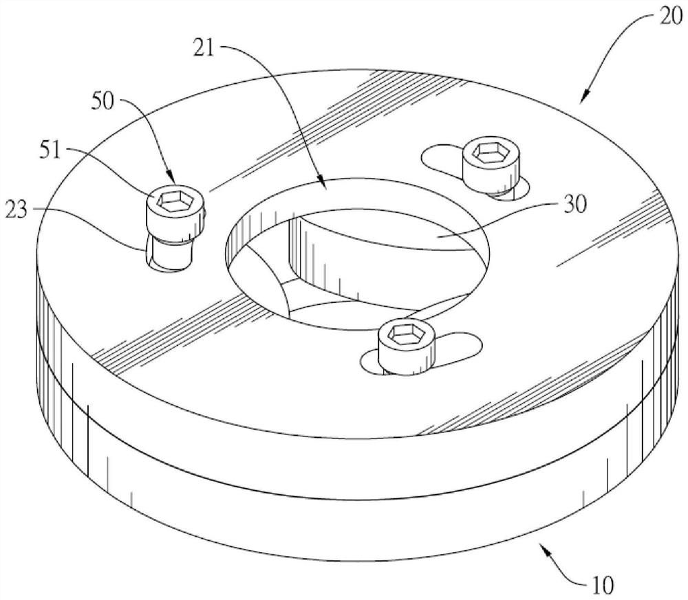
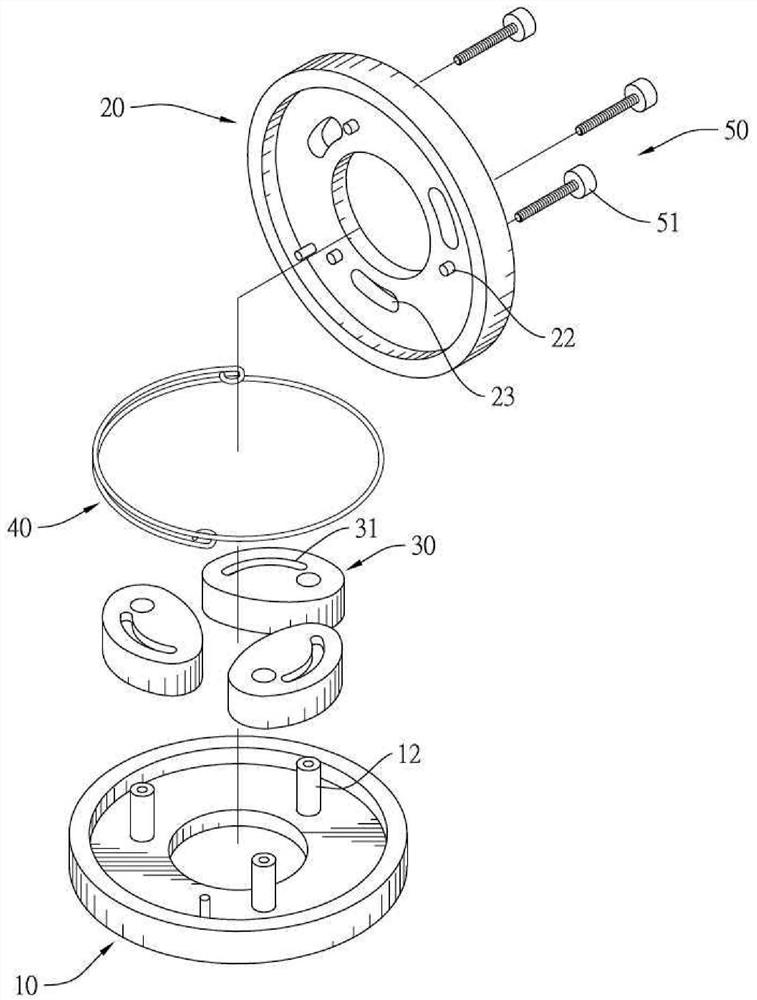
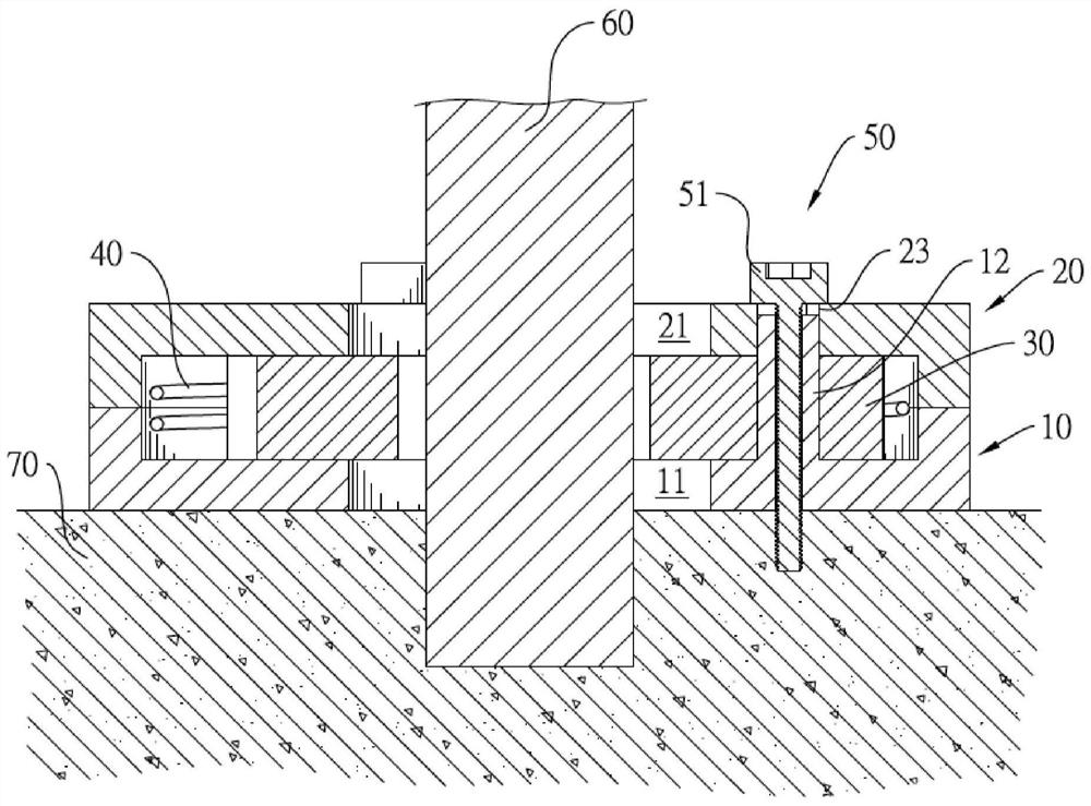
[0041] See figure 1 , figure 2 and Figure 10 As shown, the automatic closing clamping device of the present invention includes a first seat 10, a second seat 20, three clamping members 30, and an elastic element 40. The present invention passes the relative rotation of the first seat 10 and the second seat 20 to be pivotable, and the three clamps 30 can be used to set an object or discharge the object, and the present invention can be used to set it. Excessive objects, such as rod-shaped indicators 60 (hereinafter will be illustrated as illustrated by indicator lights 60), but is not limited to indicator 60 or elongated objects, can also be used to set other shapes.

[0042] See 4 and Figure 6 As shown, the aforementioned first seat 10 and the second seat 20 are disc-shaped objects, but may also be a non-circular shape; the second seat 20 is dispose...


PUM


Abstract

The invention provides an automatic closing and clamping device. The automatic closing and clamping device comprises a first seat, a second seat, a plurality of clamping pieces and an elastic element.The first seat and the second seat can rotate relatively. A plurality of protruding columns corresponding to the clamping pieces respectively are formed on the second base towards the inner space. The clamping pieces are arranged on the first base in a pivoted mode and arranged around the pivot axis of the first base and the pivot axis of the second base. Each clamping piece is provided with a sliding rail, and the protruding column is arranged in the sliding rail in a sliding mode. When the first base and the second base rotate relatively, the protruding column abuts against the inner wall face of the sliding rail so that the clamping piece can pivot towards or away from the center. The elastic element enables the first seat and the second seat to rotate relatively to enable the clampingpiece to pivot towards the center so as to achieve automatic closing, so that the clamping piece can be opened to contain an object to be clamped only by rotating the first seat and the second seat relatively, then the clamping piece can be automatically closed and clamped by releasing the hand, operation is quite easy and convenient, and the structure is simple.

Description

Technical field [0001] The present invention relates to an apparatus that holds other objects in a surrounding manner, and more particularly to a clamping device that holds other objects (e.g., rod-shaped indicators) for a long time to stabilize the object. Background technique [0002] In the prior art, there are many elongated objects to be set up, and it is necessary to further maintain a solid vertical state through a fixed device, and the rod-shaped indicator is a common example. [0003] The rod-shaped indicator is generally a subject or machine bonded below the bottom end, but only the binding of the bottom end may not be stable enough, and therefore, it is often further set of a fixing device to the indicator lamp, the fixing device is also fixed to the bottom Objects or machines, and simultaneously surround the indicator light, so that the indicator can remain upright. [0004] However, different labels or different signs may have different outer diameters, so there is a...

Claims


Application Information

Patent Timeline
Patent Type & Authority Applications(China)
IPC IPC(8): F21V21/088
CPCF21V21/088
Inventor 江铵畯叶俊良
Owner PEGATRON
Features
  • R&D
  • Intellectual Property
  • Life Sciences
  • Materials
  • Tech Scout
  • Unparalleled Data Quality
  • Higher Quality Content
  • 60% Fewer Hallucinations
Learn More