Self-cleaning power distribution cabinet

A self-cleaning technology for power distribution cabinets, which is applied in substation/power distribution device casings, electrical components, and general water supply conservation, etc., can solve the problem of high cleaning costs for power distribution cabinets

Inactive Publication Date: 2021-03-05
龙思奇
View PDF6 Cites 0 Cited by
  • Summary
  • Abstract
  • Description
  • Claims
  • Application Information

AI Technical Summary

Problems solved by technology

[0004] Based on the technical problem of high cleaning cost of existing power distribution cabinets, the present invention proposes a self-cleaning power distribution cabinet

Method used


Image

  • Self-cleaning power distribution cabinet
  • Self-cleaning power distribution cabinet
  • Self-cleaning power distribution cabinet

Examples


Embodiment 1

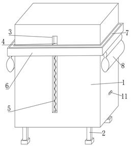
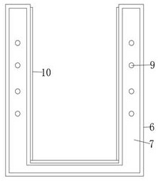
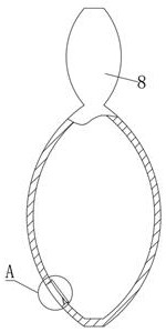
[0028] refer to Figure 1-4 , a self-cleaning power distribution cabinet, including a power distribution cabinet body 1, a plurality of legs 2 are symmetrically fixed on both sides of the bottom of the power distribution cabinet body 1 by bolts, and a first chute 3 is provided at the rear end of the power distribution cabinet body 1, and the second A slider 4 is slidably connected in the chute 3, and the bottom of the slider 4 is fixed with a first spring 5 by bolts. The water receiving plate 6 is fixed by bolts, the cross section of the water receiving plate 6 is set into a U shape, the top of the water receiving plate 6 is provided with a water receiving tank 7, and the bottom of the water receiving tank 7 is provided with a plurality of water inlet holes 9, and the bottom of the water receiving plate 6 has two holes. There are two water receiving tanks 8 fixed laterally symmetrically by bolts. The water receiving tanks 8 communicate with the water inlet holes 9. The cross s...

Embodiment 2

[0032] refer to Figure 1-7 , a self-cleaning power distribution cabinet, the top inner wall of the water outlet 12 is provided with a first groove 15, the first groove 15 is bonded with a first permanent magnet 16, the top of the top block 11 is provided with a second groove 17, the first The second permanent magnet 18 is bonded in the second groove 17, and the first permanent magnet 16 and the second permanent magnet 18 have different magnetic poles opposite to each other. Two second slide grooves 19 are arranged symmetrically on both sides of the power distribution cabinet body 1. The second chute 19 is fixed with a third spring 20 by bolts, and the outside of the third spring 20 is fixed with a block 21 by bolts. There are a plurality of third grooves 22 on the top of the arc surface of the block 21, and a plurality of varistor rollers 25 distributed in an annular array are connected to the third grooves 22 through bearing rotation. The outer surface of the varistor roller...


PUM


Abstract

The invention belongs to the technical field of power distribution cabinets, particularly relates to a self-cleaning power distribution cabinet, and provides the following scheme for solving the problem that an existing power distribution cabinet is high in cleaning cost: the self-cleaning power distribution cabinet comprises a power distribution cabinet body, a first sliding groove is formed in the rear end of the power distribution cabinet body, and a sliding block is slidably connected in the first sliding groove; a water receiving plate is fixed to the rear end of the sliding block, a water receiving groove is formed in the top of the water receiving plate, water receiving tanks are fixed to the two sides of the bottom of the water receiving plate, water outlets are formed in the innersides of the water receiving tanks, sealing plates are rotationally connected to the inner walls of the water receiving tanks, second springs are fixed between the sealing plates and the water outlets, and two sides of the power distribution cabinet body are fixedly provided with top blocks. According to the power distribution cabinet, the water receiving plate moves downwards after receiving rainwater until the top block makes contact with the sealing plate, the sealing plate is jacked open to generate a gap, water in the water receiving tank flows out, the water receiving plate and the water receiving tank rebound upwards along with reduction of gravity and move periodically, and the shell of the power distribution cabinet body is wiped and cleaned.

Description

technical field [0001] The invention relates to the technical field of power distribution cabinets, in particular to a self-cleaning power distribution cabinet. Background technique [0002] With the rapid development of the economy, industrial production and people's life are inseparable from the use of electricity, and the role of electricity is increasing, so the related power distribution equipment is also used more and more widely. Outdoor power distribution cabinet is an important power distribution equipment, which is widely used in oil exploration, oil refining, chemical industry, military industry and other dangerous environments, as well as offshore oil platforms, oil tankers and other places for general lighting and operational lighting. With the widespread use of outdoor power distribution cabinets, people's requirements for it are getting higher and higher. Therefore, outdoor power distribution cabinets must be gradually improved to adapt to the development of s...

Claims


Application Information

Patent Timeline
Patent Type & Authority Applications(China)
IPC IPC(8): H02B1/28H02B1/30H02B1/32H01F7/02E03F5/10E03B3/02B08B1/00
CPCH02B1/28H02B1/306H02B1/32B08B1/006B08B1/008H01F7/02E03B3/02E03F5/10Y02A20/108
Inventor 龙思奇
Owner 龙思奇
Why Eureka
Try Eureka