
Eureka
For R&D, Eureka makes reading and utilizing patents & technical documents easy.
Eureka AIR
Designed for self-driven R&D workflows. Generate viable solutions, solve complex R&D challenges, empower your innovation with AI.

Eureka Materials
Designed for material experts only. Revolutionize your material R&D, from search, analyze, to developing new materials.

TechResearch
Generate reliable direction feasibility study reports for your R&D in just a few steps.

TechSeek
Discover and master advanced knowledge NOW. Basics, ideas, possibilities, all at once.

TechMind
As an expert in R&D Theories, TechMind can generates customized viable solutions instantly.

TechRisk
Analyze your overall solution with one click, know your potential R&D risks in advance.

TechMonitor
Get weekly tech updates, stay abreast of the latest tech innovations and key insights.
Bone trimmer
A dressing device and dressing ring technology, applied in the field of stomatology, can solve the problems of difficulty in controlling the dressing amount of a ball drill, damage to adjacent tissues, and easy slippage, etc., and achieve the effects of preventing slippage, simplifying the difficulty of dressing, and being easy to operate.
- Summary
- Abstract
- Description
- Claims
- Application Information
AI Technical Summary
Problems solved by technology
Method used
Image

Examples
Embodiment approach 1
[0034] The present application provides a bone trimmer.
[0035] The inventors of the present application found that, in the prior art, the bone repair methods adopted often cannot achieve good results. When using a ball drill to modify the bone surface, it is easy to slip, and the damage caused will significantly increase the pain of the patient, and may cause additional bone surface or soft tissue damage. However, some conventional alternative solutions cannot completely replace the role of the ball drill. For example, doctors sometimes use rongeurs to modify the bone surface, but the convenience of tools such as rongeurs is much worse than that of ball drills. Moreover, in some narrow spaces or corners, it is difficult for the beak of the rongeur to enter the trimming space, and the trimming effect cannot be exerted in all cases.
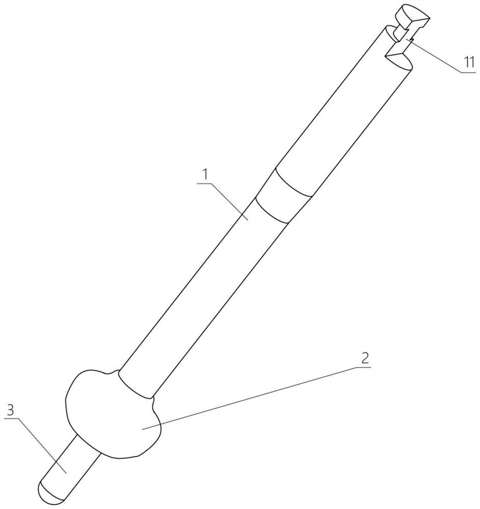
[0036] In order to solve the above problems, the first embodiment of the present application provides a bone trimmer, see figure 1 shown, inc...
Embodiment approach 2
[0055] The second embodiment of the present application provides a bone trimmer, the bone trimmer of the second embodiment is substantially the same as the bone trimmer of the first embodiment, the main difference is that in the first embodiment of the present application In the second embodiment of the present application, the guide rod 3 can be relatively fixedly connected with the bone trimming ring 2 and rotate coaxially with the bone trimming ring 2 ; while in the second embodiment of the present application, the guide rod 3 can freely rotate relative to the bone trimming ring 2 .
[0056] Although the guide rod 3 does not have the ability to grind, it will still exert force on the bone surface in the positioning hole 5 during the high-speed rotation following the bone trimming ring 2, causing discomfort to the patient. Therefore, when the guide rod 3 is set to be freely rotatable relative to the bone trimming ring 2, the rotation of the bone trimming ring 2 will not drive...
Embodiment approach 3
[0062] The second embodiment of the present application provides a bone trimmer, the bone trimmer of the third embodiment is substantially the same as the bone trimmer of the second embodiment, the main difference is that in the second embodiment of the present application Among them, the bone trimming ring 2 and the main body 1 are integrally formed; while in the third embodiment of the present application, see Figure 9 , Figure 10 As shown, the bone trimming ring 2 is formed with a sleeve hole 22 passing through the axis of rotation, and the bone trimming ring 2 is sleeved on the main body 1 through the sleeve hole 22;
[0063] An accommodating hole 12 is formed on the main body 1 at a position facing the sleeve hole 22;
[0064] The tail end of the guide rod 3 passes through the sleeve hole 22 and penetrates into the accommodating hole 12 , and the head end protrudes from the sleeve hole 22 .
[0065] Compared with the one-piece design, this solution enables the bone tr...
PUM
 Abstract
Description
Claims
Application Information
 - R&D Engineer
- R&D Manager
- IP Professional
- Industry Leading Data Capabilities
- Powerful AI technology
- Patent DNA Extraction
Browse by: Latest US Patents, China's latest patents, Technical Efficacy Thesaurus, Application Domain, Technology Topic, Popular Technical Reports.
© 2024 PatSnap. All rights reserved.Legal|Privacy policy|Modern Slavery Act Transparency Statement|Sitemap|About US| Contact US: help@patsnap.com