Multifunctional necking machine

A multi-functional, shrinking technology, applied in the field of shrinking machines, can solve the problems of inability to apply force to the pipeline, concave lines, extrusion, etc., and achieve the effect of reducing surface friction and avoiding overfitting.

Inactive Publication Date: 2021-03-09
广州九岳天装饰工程有限公司
View PDF0 Cites 0 Cited by
  • Summary
  • Abstract
  • Description
  • Claims
  • Application Information

AI Technical Summary

Problems solved by technology

[0003] Based on the inventors' discovery above, existing methods mainly have the following deficiencies, such as: the clamping ring of the necking machine is assembled from multi-end arc bars, and when the clamp ring is not shrinking, a There are equidistant gaps, and the gap between the clamping rings cannot exert force on the pipe when it is clamped and contracted, causing the clamping strips at both ends to squeeze the inner side of the pipe wall at the gap and cause a depression during the simultaneous contraction process texture

Method used


Image

  • Multifunctional necking machine
  • Multifunctional necking machine
  • Multifunctional necking machine

Examples


Embodiment 1

[0025] as attached figure 1 to attach Figure 5 Shown:

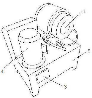
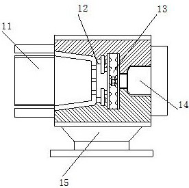
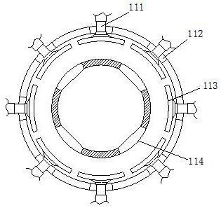
[0026] The invention provides a multifunctional necking machine, the structure of which comprises a necking device 1, a mounting base 2, a control panel 3, and a motor 4. The necking device 1 is bolted directly above the mounting base 2, and the mounting base 2. The outer end surface is connected to the control panel 3 by welding, and the control panel 3 is embedded and installed directly under the motor 4, and the motor 4 is embedded and installed on the left side of the necking device 1; the necking device 1 It includes a clamping mechanism 11, an inlay plate 12, a gear rod 13, a power shaft 14, and an embedded seat 15. The clamping mechanism 11 is inlaid and installed on the left side of the inlay plate 12, and the right end surface of the inlay plate 12 is Connected to the gear rod 13, the gear rod 13 is engaged with the power shaft 14, the power shaft 14 is located on the right side of the clamping mechanism 11, a...

Embodiment 2

[0033] as attached Figure 6 to attach Figure 7 As shown: the extension device 131 includes a chute 311, a limit shaft 312, a movable shaft 313, an elastic rope 314, and an extension plate 315. The bit shaft 312 is located on the left side of the movable shaft 313, and the movable shaft 313 is movably mounted on the inner upper end surface of the extension device 131, and the left end surface of the elastic rope 314 is embedded and connected to the left side of the extension plate 315. Below, the extension plate 315 is movably connected to the limit shaft 312. The outer contour of the extension plate 315 is arc-shaped, and the distance from the small end of the left upper surface is a plane. When the extension plate 315 is squeezed , can slide to the left port in the sliding groove 311 to extend the extrusion area.

[0034] Wherein, the extension plate 315 includes a second inlay groove 151, an inlay plate 152, a second chute 153, and a movable plate 154. The second inlay gro...


PUM


Abstract

The invention discloses a multifunctional necking machine. The multifunctional necking machine structurally comprises necking equipment, a mounting base, a control panel and a motor, wherein the necking equipment is in bolted connection to the position right above the mounting base, the outer side end surface of the mounting base is connected with the control panel through welding, the control panel is fixedly arranged right below the motor in an embedded mode, and the motor is embedded and clamped to the left side of the necking equipment. When turning balls are subjected to overlarge extrusion force, a rubber block is sunken inwards to change the diameters of the inner contours of hollow grooves, so that the outer contours of the turning balls are changed, and rotation is formed in the continuous extrusion process of the turning balls to change the connecting end point between a movable plate and a metal pipeline, so that the surface friction force between the movable plate and the metal pipeline is reduced, the force application position of the connecting end face of the movable plate and the metal pipeline is changed, and the situation that the area of the compressed end face is unchanged to form extrusion concave lines on the pipeline at the gap due to the fact that the connecting end face is excessively attached is avoided.

Description

technical field [0001] The invention belongs to the field of necking machines, and more specifically relates to a multifunctional necking machine. Background technique [0002] Neck shrinking machine is a kind of equipment for partial reduction of metal pipes and hot-melt plastic pipes by using multi-terminal clamping rings. Through the indirect interpenetrating processing of the inner and outer rings of the clamping rings, the pipes can be pushed together with the pipes at the same time. Cooperating with gradually changing the diameter of the pipe mouth enables splicing between two pipes. [0003] Based on the inventors' discovery above, existing methods mainly have the following deficiencies, such as: the clamping ring of the necking machine is assembled from multi-end arc bars, and when the clamp ring is not shrinking, a There are equidistant gaps, and the gap between the clamping rings cannot exert force on the pipe when it is clamped and contracted, causing the clampin...

Claims


Application Information

Patent Timeline
Patent Type & Authority Applications(China)
IPC IPC(8): B21D41/04
CPCB21D41/04
Inventor 曹姗姗
Owner 广州九岳天装饰工程有限公司
Why Eureka
Try Eureka