
Connecting rod used for engine crankshaft

An engine and connecting rod technology, applied in the direction of engine components, connecting rods, shafts, etc., can solve the problems of large force on the tightening screw, easy damage, affecting the service life of the connecting rod, etc., and achieve the effect of improving the service life and preventing damage.

Pending Publication Date: 2019-08-20
戴国春
View PDF5 Cites 1 Cited by
  • Summary
  • Abstract
  • Description
  • Claims
  • Application Information

AI Technical Summary

Problems solved by technology

[0004] The invention provides a connecting rod used on the engine crankshaft to solve the problem that when the existing connecting rod is pulled and swayed by the crankshaft, the two fastening screws at the big head hole are under a large force, are easily damaged, and affect the service life of the connecting rod, etc. shortcoming

Method used


Image

  • Connecting rod used for engine crankshaft
  • Connecting rod used for engine crankshaft
  • Connecting rod used for engine crankshaft

Examples


Embodiment Construction

[0016] Specific embodiments of the present invention will be described below with reference to the accompanying drawings. In order to provide a comprehensive understanding of the present invention, many details are described below, but it will be apparent to those skilled in the art that the present invention can be practiced without these details. Known circuits, components, methods and processes will not be described in detail below.

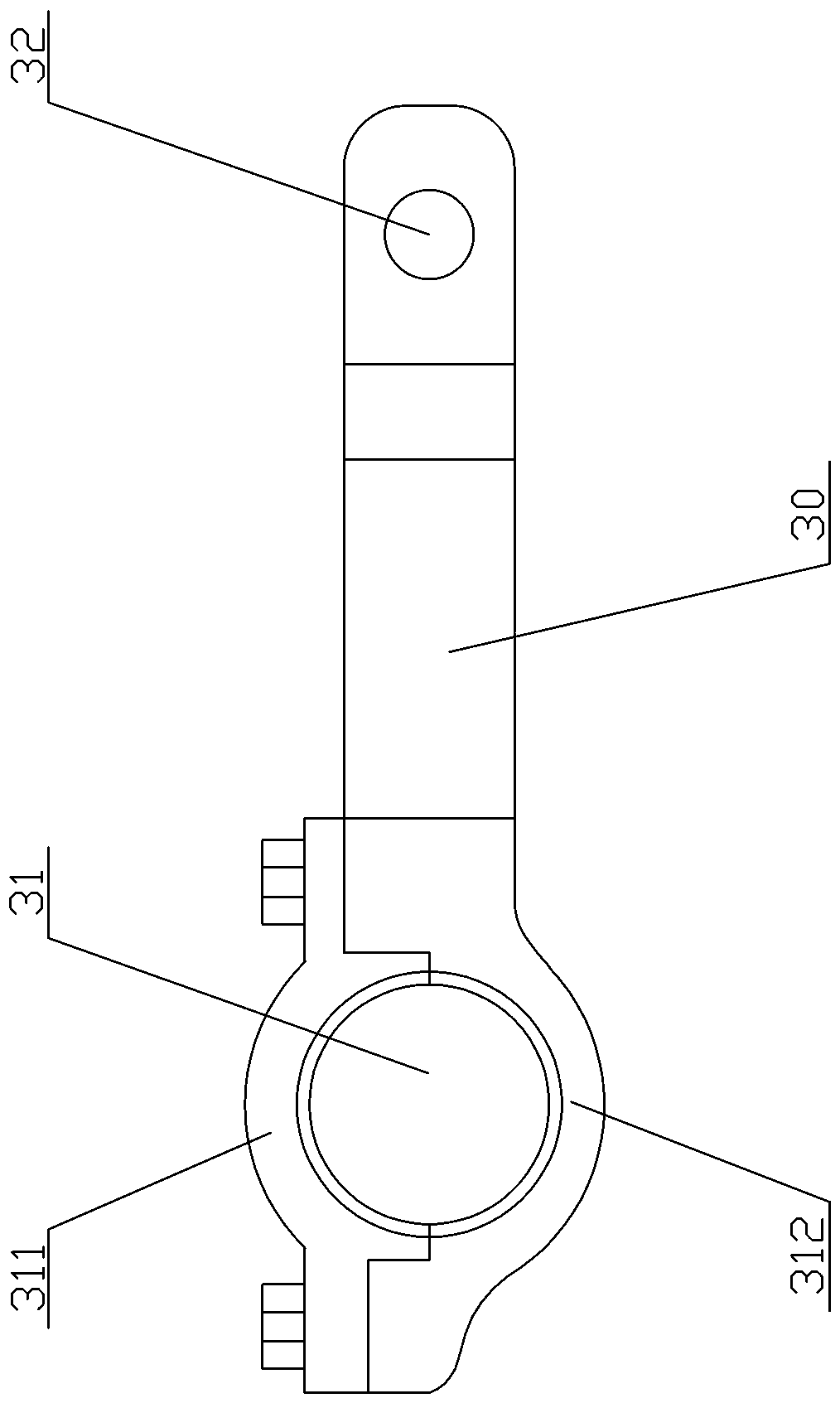
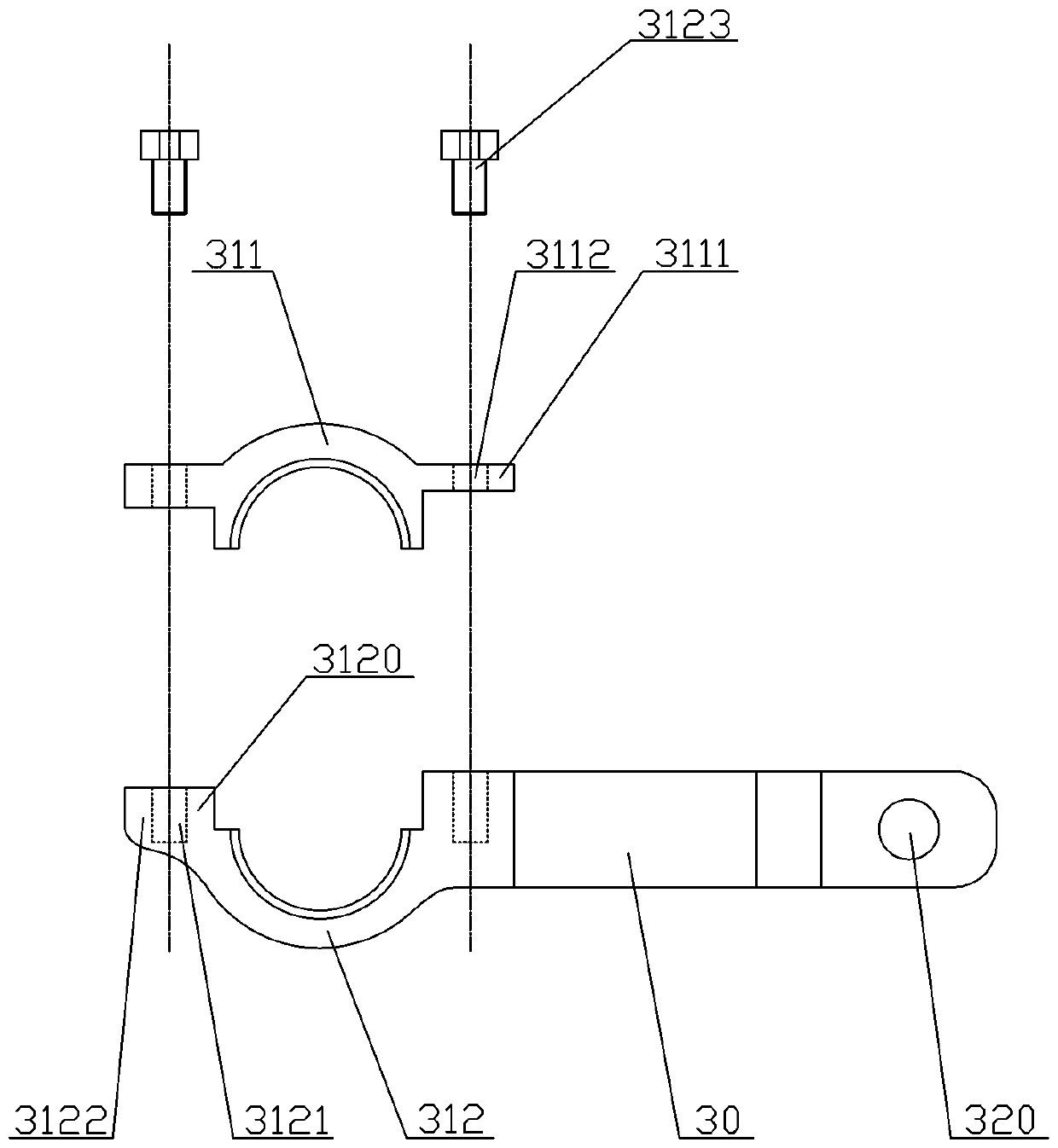
[0017] A connecting rod used on an engine crankshaft, refer to Figure 2 to Figure 4 , including a connecting rod main body 30, the two ends of the connecting rod main body 30 are respectively provided with a large end hole 31 and a small end hole 32, and the large end hole 31 is connected with the connecting rod journal of the crankshaft. Wherein the big head hole 31 is made up of upper semicircular groove body 311 and lower semicircular groove body 312. Sections are parallel. The left and right sides of the lower semicircular tank body 31...


PUM


Abstract

A connecting rod used for an engine crankshaft comprises a connecting rod main body. A big-head hole and a small-head hole are separately formed in the two ends of the connecting rod main body. The big-head hole is connected with a connecting-rod shaft neck of the crankshaft and is composed of an upper half circular groove and a lower half circular groove, wherein a combination plane between the upper half circular groove and the lower half circular groove is parallel to the cross section where the axis of the connecting rod is located, two lower connecting parts each provided with an upward protruding step are separately formed on the left side and the right side of the lower half circular groove, two upper connecting parts matched with the lower connecting parts are separately formed onthe left side and the right side of the upper half circular groove, and the upper connecting parts are detachably connected with the lower connecting parts. According to the connecting rod, the stressposition of a traditional pull rod is changed, and the stress is applied to the protruding steps of the connecting rods when the crankshaft rotates, so that damage to a fastening screw is prevented,and the service life of the connecting rod is greatly improved.

Description

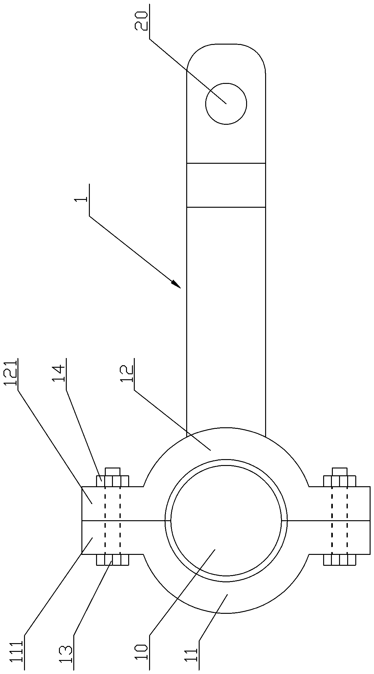
technical field [0001] The invention relates to the technical field of engines, and more specifically refers to a connecting rod used on an engine crankshaft. Background technique [0002] The crank connecting rod mechanism is the mechanism by which the engine generates and transmits power, through which the linear reciprocating motion of the piston is converted into the rotational motion of the crankshaft to output power. It includes pistons, piston pins, connecting rods, crankshafts and cylinder blocks, etc. [0003] refer to figure 1 At present, the existing connecting rod includes a connecting rod main body 1, and the two ends of the connecting rod main body 1 are respectively provided with a large end hole 10 and a small end hole 20, wherein the large end hole 10 is connected with the connecting rod journal of the crankshaft. Big head hole 10 is made up of left semicircular groove body 11 and right semicircular groove body 12, two left connecting parts 111 are respect...

Claims


Application Information

Patent Timeline
Patent Type & Authority Applications(China)
IPC IPC(8): F16C7/02
CPCF16C7/023F16C2360/00
Inventor 戴国春戴毅柔戴秋乙
Owner 戴国春
Learn More