Cubesat deploying device based on 3D printing

A 3D printing, cubic technology, applied in the directions of artificial satellites, space navigation ground equipment, space navigation equipment, etc., can solve the problem of unadjustable launch speed, etc., to achieve the effect of convenient hoisting and placement, good applicability

Active Publication Date: 2021-03-09
星众空间(北京)科技有限公司
View PDF7 Cites 1 Cited by
  • Summary
  • Abstract
  • Description
  • Claims
  • Application Information

AI Technical Summary

Problems solved by technology

[0003] The purpose of the present invention is to provide a 3D printing-based CubeSat deployer to solve the problem that the launch speed of the CubeSat deployer in the prior art cannot be adjusted

Method used


Image

  • Cubesat deploying device based on 3D printing
  • Cubesat deploying device based on 3D printing
  • Cubesat deploying device based on 3D printing

Examples


Embodiment Construction

[0028] The following will clearly and completely describe the technical solutions in the embodiments of the present invention with reference to the drawings in the embodiments of the present invention.

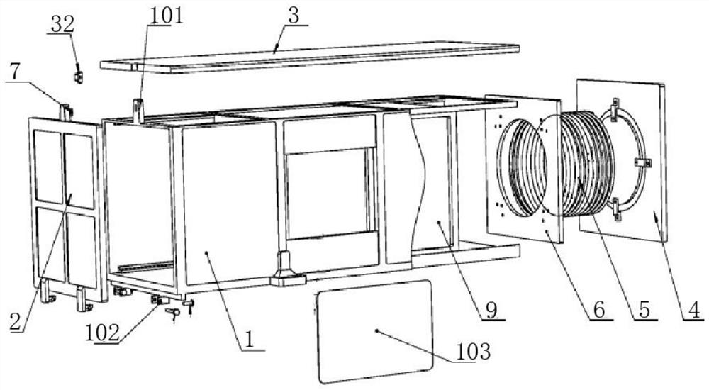
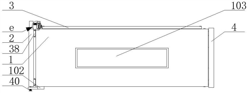
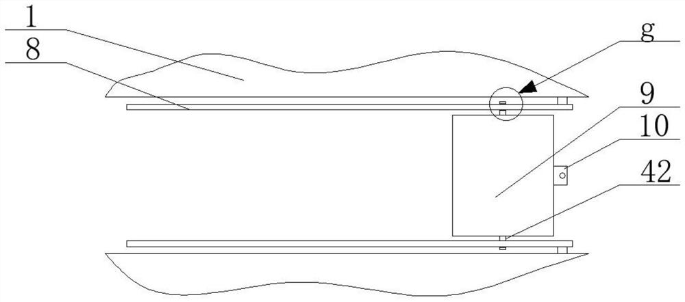
[0029] see figure 1 , figure 2 , image 3 , Figure 4 , Image 6 with Figure 7 , a CubeSat deployer based on 3D printing, including a box body 1 and a door 2 connected to it by hinges, wherein the box body 1, door 2, top plate 3 and back plate 4 are printed using 3D selective laser Melting technology, through the fusion of the parts to realize the additive manufacturing step, the manufacturing is carried out on the support plate, and the metal powder is completely melted under the heat of the laser beam, and then formed after cooling and solidification. The upper end of the box body 1 is bolted to the top plate 3. There is an opening 12 on the box body 1, and the top plate 3 is inserted into the opening 12. There are four main thread grooves 13 on the outer end surface ...


PUM


Abstract

A cubesat deploying device based on 3D printing is disclosed in the invention, and comprises a box body and a cabin door arranged on the box body, a back plate is arranged on one side of the box body,a telescopic mechanism is arranged on one side of the back plate, a spring is arranged on one side of the telescopic mechanism, a push plate is arranged on one side of the spring, an unlocking mechanism is arranged on the box body, and a fixing pin is arranged on the cabin door. Main sliding rails are symmetrically arranged in the box body, a cubesat is connected to the main sliding rails in a sliding mode, connecting blocks are symmetrically arranged on one side of the cubesat, a connecting mechanism is arranged on the push plate, the connecting blocks are arranged on the connecting mechanism, and an electromagnetic lock is arranged in the connecting mechanism. The telescopic movement of an electric lifting rod enables a connecting plate to move horizontally, the movement of the connecting plate can adjust the compression amount of the spring, so that the spring thrust value of the spring to the push plate is changed; and a pressure sensor arranged on the push plate can accurately control the spring thrust generated by the spring, so the device has the characteristic that the launching speed of the cubesat deploying device is adjustable.

Description

technical field [0001] The invention belongs to the technical field of aerospace equipment, and in particular relates to a 3D printing-based CubeSat deployer. Background technique [0002] At present, microsatellites have received extensive attention, especially CubeSats. Cube satellite refers to a cube-shaped satellite with an external dimension of 10cm×10cm×10cm as a basic structural unit, which can be expanded on one axis or multiple axes to form different types of configurations such as 1U, 2U, 3U, etc., and its weight is not more than 100kg . Cube satellites are generally launched by piggyback, that is, they are launched on the same carrier rocket as large satellites. This launch method requires the satellite to be able to use a variety of rocket platforms, which puts high demands on the CubeSat developer. Therefore, it is very important to develop a CubeSat launch deployer as the interface between the CubeSat and the launch vehicle. On the one hand, this deployer me...

Claims


Application Information

Patent Timeline
Patent Type & Authority Applications(China)
IPC IPC(8): B64G5/00B64G1/10
CPCB64G5/00B64G1/10B33Y80/00
Inventor 薛国粮赵冲于晓洲胡鑫白瑞雪
Owner 星众空间(北京)科技有限公司
Why Eureka
Try Eureka