
Multi-angle steering control platform for corrugated steel web prestressed box girder bridge

A corrugated steel web and control platform technology, applied in bridges, bridge construction, erection/assembly of bridges, etc., can solve the problems of inconvenient angle adjustment, incomplete connection of concrete box beams, angle deviation, etc., and achieve easy splicing and installation. Effect

Pending Publication Date: 2021-03-09
CHUZHOU VOCATIONAL & TECHN COLLEGE
View PDF9 Cites 2 Cited by
  • Summary
  • Abstract
  • Description
  • Claims
  • Application Information

AI Technical Summary

Problems solved by technology

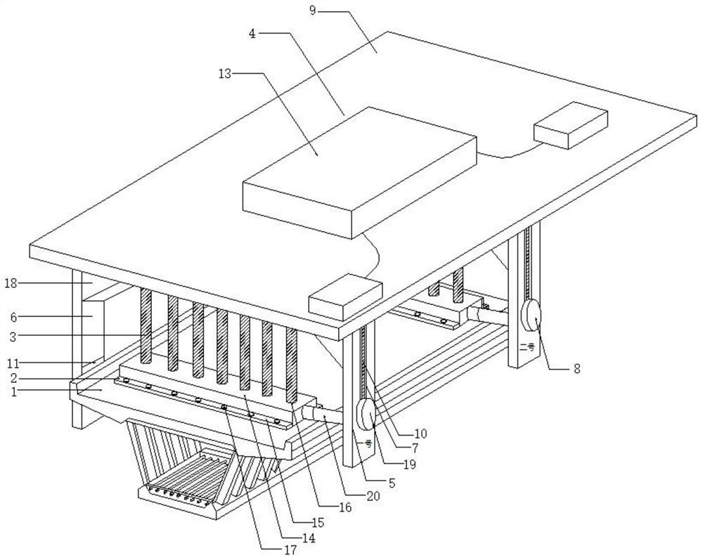
[0004] The purpose of the present invention is to provide a multi-angle steering control platform for corrugated steel web prestressed box girder bridge, which solves the problem of connecting with the concrete box girder below by using steel cables and carrying out overhead displacement generally through the bridge erecting machine. When moving to the position to be installed, the lower processing will be carried out. However, during the moving process, the steel cable will drive the concrete box girder below to have an angular offset, which will easily lead to incomplete butt joints between the concrete box girders, and it is inconvenient to adjust the angle. this technical issue

Method used


Image

  • Multi-angle steering control platform for corrugated steel web prestressed box girder bridge
  • Multi-angle steering control platform for corrugated steel web prestressed box girder bridge
  • Multi-angle steering control platform for corrugated steel web prestressed box girder bridge

Examples


Embodiment Construction

[0019] The following will clearly and completely describe the technical solutions in the embodiments of the present invention with reference to the accompanying drawings in the embodiments of the present invention. Obviously, the described embodiments are only some, not all, embodiments of the present invention. Based on the embodiments of the present invention, all other embodiments obtained by persons of ordinary skill in the art without making creative efforts belong to the protection scope of the present invention.

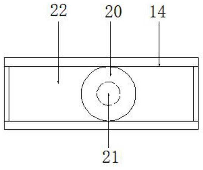
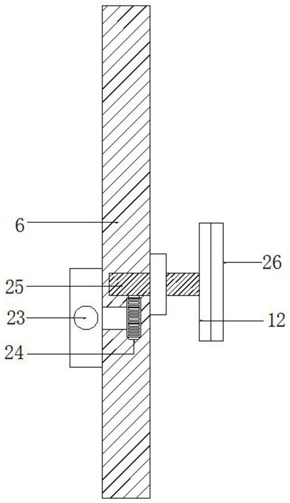
[0020] see Figure 1-3 , the present invention provides a technical solution: a multi-angle steering control platform for corrugated steel web prestressed box girder bridges, including a concrete box girder 1, and two sets of grasping plates are symmetrically installed at both ends of the concrete box girder 1 2. There are several groups of steel cables 3 evenly connected above the two groups of grasping plates 2, and the bridge erecting machine body 4 is arra...


PUM

PropertyMeasurementUnit
Thicknessaaaaaaaaaa

Abstract

The invention discloses a multi-angle steering control platform for a corrugated steel web prestressed box girder bridge. The multi-angle steering control platform comprises a concrete box girder, twosets of grabbing plates are symmetrically installed at the two ends of the concrete box girder, a plurality of sets of steel cables are evenly connected to the upper portions of the two sets of grabbing plates, and a bridge erecting machine body is arranged above the steel cables. The lower surface of the bridge girder erection machine body is fixedly connected with a plurality of sets of steel cables, two sets of driving supporting plates are symmetrically installed on one side of the bridge girder erection machine body, two sets of limiting supporting plates are symmetrically installed on the other side of the bridge girder erection machine body, guide grooves are longitudinally formed in the middles of the driving supporting plates, hydraulic pushers are movably installed in the guidegrooves, and winches are arranged above the guide grooves. The operation platform specially used for adjusting the angle of the box girder is designed at the joint of the bridge girder erection machine and the concrete box girder, and through the driving mechanism installed on one side of the bridge girder erection machine and the limiting mechanism installed on the other side of the bridge girdererection machine, accurate angle adjustment can be conducted on the concrete box girder; and the concrete box girders are accurately spliced and mounted.

Description

technical field [0001] The invention relates to the technical field of bridge construction, in particular to a multi-angle steering control platform for corrugated steel web prestressed box girder bridges. Background technique [0002] Bridges generally refer to structures erected on rivers, lakes and seas to allow vehicles and pedestrians to pass smoothly. In order to adapt to the modern high-speed development of the transportation industry, bridges are also extended to buildings that cross mountain streams, poor geology or meet other transportation needs to make traffic more convenient. A bridge is generally composed of a superstructure, a substructure, a support and ancillary structures. The superstructure is also called a bridge span structure, which is the main structure for crossing obstacles; the substructure includes abutments, piers and foundations; Or the force transmission device installed at the supporting place of the abutment; the auxiliary structures refer to...

Claims


Application Information

Patent Timeline
IPC IPC(8): E01D21/00E01D2/04
CPCE01D21/00E01D2/04
Inventor 尤超梁冠军黄雯雯李西张涛冯环林祖宏王倩倩朱国涛
Owner CHUZHOU VOCATIONAL & TECHN COLLEGE
Learn More