
Fuel filter

A fuel filter and filter element technology, which is applied in the direction of machines/engines, liquid fuel feeders, fuel heat treatment devices, etc., can solve the problems of difficult disassembly, increased difficulty of assembly process, labor, and long time, etc., to achieve The effect of reducing the difficulty of processing technology, reducing sealing failure points, and reducing the number of channels

Pending Publication Date: 2021-03-09
无锡亿利环保科技有限公司 +1
View PDF0 Cites 2 Cited by
  • Summary
  • Abstract
  • Description
  • Claims
  • Application Information

AI Technical Summary

Problems solved by technology

In this way, it is necessary to process the snap-fit ​​groove on the inner wall of the one-way valve channel, which increases the difficulty of processing the base; moreover, after the valve seat is snapped, it is difficult to take it out. When the one-way valve needs to be replaced, it is difficult to disassemble and assemble, which requires more labor and time, and the cost of labor and time is higher
[0006] (3) The filter element assembly of the fuel filter is usually placed in the casing as a whole, and then the casing is screwed onto the base through thread fit. At this time, the upper end of the filter element assembly is inserted into the central channel of the base; Assembly method, the assembly accuracy between the filter element assembly and the base needs to be determined indirectly through the assembly accuracy between the shell and the base, that is, it is first necessary to ensure a high assembly accuracy between the filter element assembly and the shell, in order to ensure that the shell is assembled to When it is on the base, the upper end of the filter element assembly can be accurately inserted into the central channel of the base. If the assembly between the assembled filter element assembly and the shell is out of tolerance, it will affect the subsequent assembly and maintenance between the shell, filter element assembly and the base. Coordination, this method puts forward higher requirements on the assembly accuracy between the filter element assembly and the shell, which increases the difficulty of the assembly process; The requirements are high, that is, the filter element assembly is closely matched with the shell, and the filter element assembly is basically placed in the shell as a whole. When disassembling and replacing the filter element assembly, it is difficult to take the filter element assembly out of the shell. The labor and time are more, and the labor cost and time cost are higher

Method used


Image

  • Fuel filter
  • Fuel filter
  • Fuel filter

Examples


Embodiment Construction

[0052] The specific implementation manner of the present invention will be described below in conjunction with the accompanying drawings.

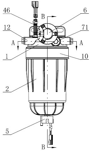
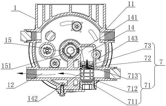
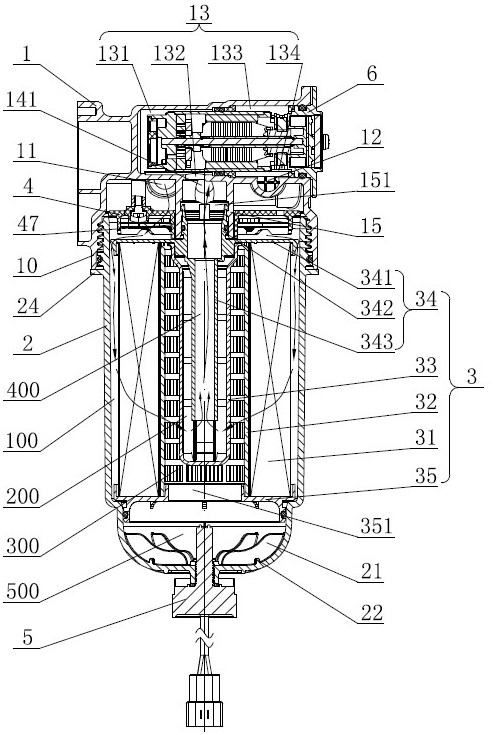
[0053] Such as figure 1 , image 3 , Figure 4 As shown, the base 1 of the present invention is a metal piece, and the upper part of the base 1 is provided with an oil inlet pipe 11 and an oil outlet pipe 12; the lower part of the base 1 has a sleeve part 10, and an internal thread is provided on the sleeve part 10. The casing 2 is fixed, and the filter element assembly 3 is arranged in the casing 2. In the inner cavity of the casing 2, the cavity located outside the filter element assembly 3 in the circumferential direction is the dirty oil cavity 100, and the cavity located below the filter element assembly 3 is the oil collection cavity. The water cavity 500, the filter element assembly 3 has a clean oil cavity 200, a hydrophobic cavity 300 and a second central channel 400 inside, the hydrophobic cavity 300 is connected to the water c...


PUM


Abstract

The invention discloses a fuel filter which comprises a base, a shell and a filter element assembly, an oil inlet pipe and an oil outlet pipe are arranged on the upper portion of the base, and a sleeve part is arranged on the lower portion of the base; the shell is connected to the sleeve part, and the filter element assembly is arranged in the shell; a central vertical pipe of the base is provided with a vertical first central channel; an electric pump is inserted into an electric pump channel in the base, and a one-way valve is arranged in a one-way valve channel; and the one-way valve channel directly communicates with the first central channel through a second oil inlet, and a channel body of the one-way valve channel intersects with a channel body of the oil outlet pipe to form a second oil outlet. According to the fuel filter, the one-way valve channel directly communicates with the first central channel through one inclined hole, the number of channels in the base is reduced, use of sealing parts matched with the channels is reduced, potential sealing failure points are reduced, the machining process difficulty of the base is lowered, the control difficulty of the machiningprecision is lowered, and a deviation is avoided.

Description

technical field [0001] The invention relates to the technical field of fuel filters for vehicles, in particular to a fuel filter. Background technique [0002] The fuel pre-filter is set in the engine fuel supply system, and is used to filter out impurities, water and other pollutants in the fuel, and then input it into the fuel delivery pump and fuel injector, so as to avoid excessive wear and tear of important parts such as fuel delivery pump and fuel injector. More or blockage and other problems to ensure the normal operation of the engine. [0003] The existing fuel filter with electric pump has the following problems: [0004] (1) There is a one-way valve on the base of the fuel filter, and the channel where the electric pump is placed on the base communicates with the channel where the one-way valve is placed. On the existing base, the one-way valve is usually set directly below the electric pump, that is, the one-way valve channel is located below the electric pump ...

Claims


Application Information

Patent Timeline
Patent Type & Authority Applications(China)
IPC IPC(8): F02M37/48F02M37/44F02M37/34F02M37/42F02M37/30F02M37/24F02M31/125F02N19/04
CPCF02M37/48F02M37/44F02M37/34F02M37/42F02M37/30F02M37/24F02M31/125F02N19/04F02N2019/002
Inventor 覃文豪顾晶晶张金玲李权汤金鹏王磊
Owner 无锡亿利环保科技有限公司
Learn More