Oil dipstick with high-reliability sealing structure
A technology of sealing structure and reliability, applied in the fuel tank of the power plant, the level indicator of the level member, the buoy liquid level indicator, etc., can solve the problems such as life and reliability limitation, corrosion and failure of the sealing O-ring , to achieve high reliability and sealing effect
- Summary
- Abstract
- Description
- Claims
- Application Information
AI Technical Summary
Problems solved by technology
Method used
Image
Examples
Embodiment 1
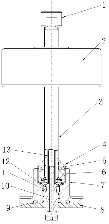
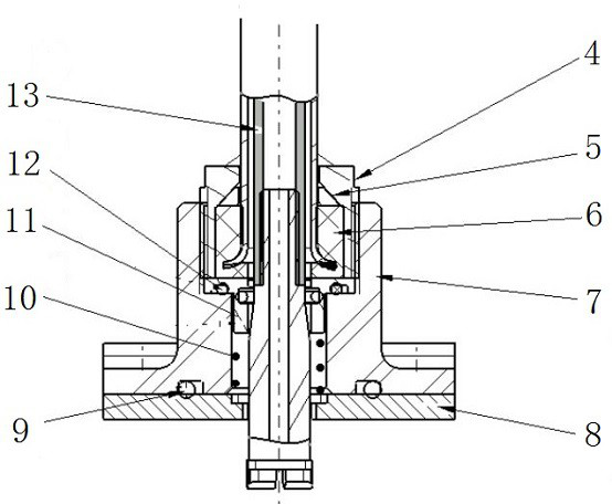
[0021] An oil dipstick with a high reliability sealing structure, combined with figure 1 with figure 2 As shown, it is installed in the fuel tank and passes through the lower wall plate 8 of the fuel tank, including the magnetic float assembly 2, the guide rod 3, the interface cavity 4, the base support 7, the upper first O-ring 9, and the scale rod assembly 13;
[0022] The base support 7 is fixedly connected with the lower wall plate 8 of the fuel tank by screws, and the first O-ring 9 on the upper part is located between the base support 7 and the lower wall plate 8 of the fuel tank;
[0023] The base support 7 is a hollow structure, and the hollow structure is divided into an interface cavity 4 located at the upper end of the hollow structure and a cylindrical lower cavity located at the lower end;
[0024] The guide rod 3 is installed in the fuel tank, the bottom port of the guide rod 3 is in the shape of a flared horn, and a rubber pad 6 is installed in the interface ...
Embodiment 2
[0028] On the basis of above-mentioned embodiment 1, in order to realize the present invention better, combine figure 1 with figure 2 As shown, further, it also includes a spring 10, a blocking sleeve 11, a second lower O-ring 12 and a rubber strip 5; Self-locking structure; the block cover 11 is arranged between the upper end of the cylindrical lower cavity and the scale rod assembly 13, the block cover 11 is an annular sleeve, and is located above the spring 10 in the cylindrical lower cavity The lower second O-ring 12 is located at the bottom of the interface cavity 4 ports and is fixedly connected to the upper end of the block sleeve 11, and the diameter of the central hole of the lower second O-ring 12 is the same as the diameter of the scale rod assembly 13 , the radius of the outer ring of the lower second O-ring 12 is the same as the radius of the bottom port of the interface cavity 4; the rubber strip 5 has a shielding layer and is located in the trumpet-shaped uppe...
Embodiment 3
[0032] On the basis of any one of the above-mentioned embodiments 1-2, in order to better realize the present invention, in combination figure 1 with figure 2 As shown, further, the rubber pad 6 is integrally installed with the bottom port of the guide rod 3, and is fixed in the interface cavity 4 through the interface thread, and thread glue is applied to the interface thread; the interface cavity 4 and Between the guide rods 3, a sealant solution capable of curing at room temperature is coated.
[0033] Working principle: The guide rod 3 and the interface cavity 4 can be fixed more tightly through the interface thread, thereby enhancing the reliability of the fuel tank, and the thread glue is applied on the interface thread to make the interface more tightly sealed.
[0034] Other parts of this embodiment are the same as those of any one of Embodiments 1-2 above, so details are not repeated here.
PUM
 Abstract
Description
Claims
Application Information
 - R&D
- Intellectual Property
- Life Sciences
- Materials
- Tech Scout
- Unparalleled Data Quality
- Higher Quality Content
- 60% Fewer Hallucinations
Browse by: Latest US Patents, China's latest patents, Technical Efficacy Thesaurus, Application Domain, Technology Topic, Popular Technical Reports.
© 2025 PatSnap. All rights reserved.Legal|Privacy policy|Modern Slavery Act Transparency Statement|Sitemap|About US| Contact US: help@patsnap.com


