Velcro adhesion experiment device
An experimental device and Velcro technology, applied in the direction of measuring devices, mechanical devices, instruments, etc., can solve the problems of poor detection effect, time-consuming and laborious, etc., and achieve the effect of improving the detection effect
- Summary
- Abstract
- Description
- Claims
- Application Information
AI Technical Summary
Problems solved by technology
Method used
Image

Examples
Embodiment 1
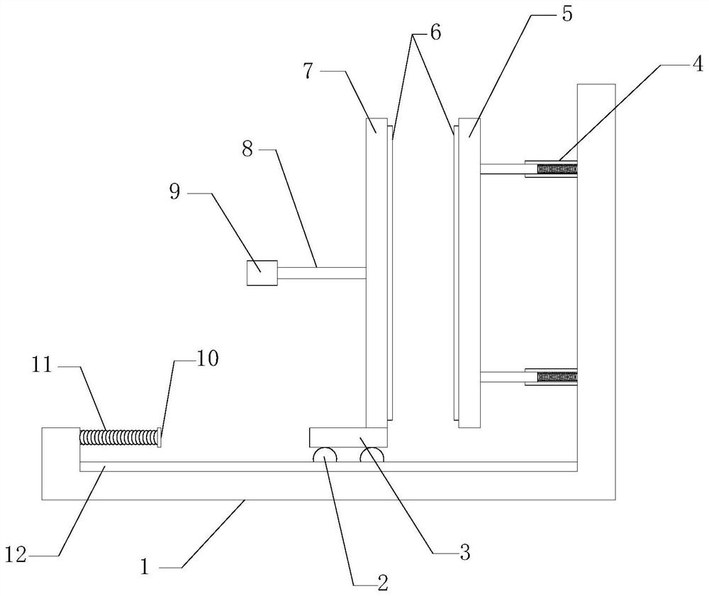
[0022] see Figure 1-Figure 4 , a Velcro bonding experimental device, including a chassis 1; including a slide rail 12, a fixed plate 5, a base 3, a movable plate 7, a handle 9 and a force plate 10, and the slide rail 12 is arranged in the chassis 1 At the bottom, the fixed plate 5 is connected to the side wall of the chassis 1 through the rebound mechanism 4, the base 3 is slidably connected to the slide rail 12 through the pulley 2, the movable plate 7 is fixedly connected to the base 3, and the handle 9 The connecting rod 8 is fixedly connected to the movable plate 7 , and the stressed plate 10 is connected to a side of the chassis 1 away from the fixed plate 5 through the first spring 11 .
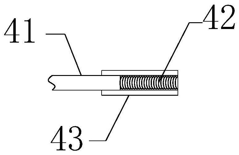
[0023] As an improvement of the above scheme, the rebound mechanism 4 includes a directional tube 43, a telescopic rod 41 and a second spring 42, the directional tube 43 is fixedly arranged on the side wall of the chassis 1, and one end of the telescopic rod 41 is connected to the fixe...
Embodiment 2
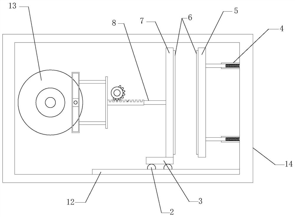
[0027] As the improvement scheme of above-mentioned scheme, also comprise box body 14 and auxiliary experimental mechanism 13, described box body 14 replaces chassis 1, is arranged on the outside of equipment, and box body 14 side is hinged with box door, described auxiliary experimental mechanism 13 It is used to replace the handle 9, the first spring 11 and the force plate 10, and drives the movable plate 7 to move away from the fixed plate 5 first and then approach the fixed plate 5.
[0028] As an improvement of the above scheme, the auxiliary experimental mechanism 13 includes a rack 1307, a motor 1305, a gear, a rotating shaft 1302, a turntable 1301, a torsion spring 1311, a slide bar 1304, a pin shaft 1310, a slider 1303, a push rod 1309 and a loading rod. Plate 1308, the rack 1307 is slidingly connected inside the box body 14, and the rack 1307 is fixedly connected to the connecting rod 8, the motor 1305 is arranged inside the box body 14, and the gear is arranged on th...
PUM
 Abstract
Description
Claims
Application Information