
Intelligent roof photovoltaic panel and mounting structure thereof

An installation structure and photovoltaic panel technology, applied in the support structure of photovoltaic modules, photovoltaic modules, photovoltaic power generation and other directions, can solve the problems affecting photovoltaic power generation efficiency, deposition on the surface of photovoltaic panels, easy accumulation on photovoltaic panels, etc., to improve the service life. As well as maintenance efficiency, easy replacement and maintenance, and the effect of ensuring installation firmness

Pending Publication Date: 2021-03-09
宁波锦锐能源科技有限公司
View PDF5 Cites 0 Cited by
  • Summary
  • Abstract
  • Description
  • Claims
  • Application Information

AI Technical Summary

Problems solved by technology

[0003] However, when the existing roof photovoltaic panels are used, especially in some areas with arid natural environment and many windy sands, due to long-term use, a large amount of dust is deposited on the surface of the photovoltaic panels, which seriously affects the efficiency of photovoltaic power generation. , snow is easy to accumulate on photovoltaic panels, which will also affect its power generation efficiency. Therefore, for the cleaning of dust and snow, most of them are cleaned manually or mechanically. Manual cleaning is more laborious, while the cost of mechanical cleaning is too high, and When installing the existing photovoltaic panels on the roof, the photovoltaic panels and the installation frame are mostly fixed by bolts, which is too cumbersome

Method used


Image

  • Intelligent roof photovoltaic panel and mounting structure thereof
  • Intelligent roof photovoltaic panel and mounting structure thereof
  • Intelligent roof photovoltaic panel and mounting structure thereof

Examples


Embodiment 2

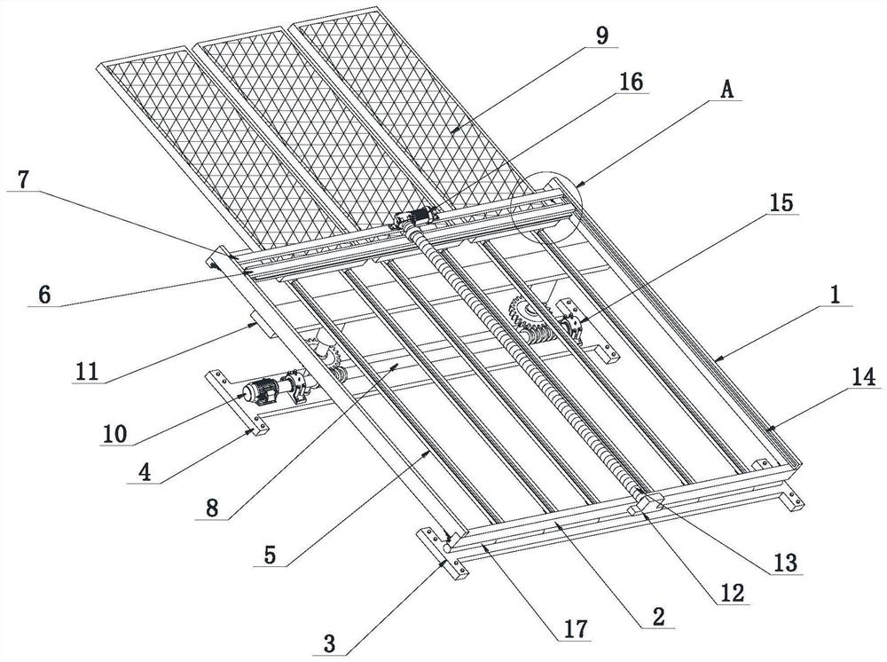
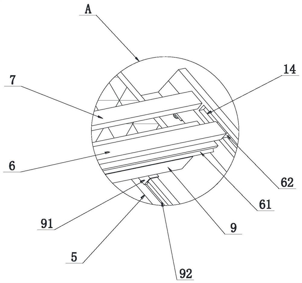
[0037] see Figure 6-10 , the difference from Embodiment 1 is that a limiting mechanism 93 is provided between the connecting seat 91 and the slide rail 92; the limiting mechanism 93 includes a pair of blocking blocks 93-1, a pair of grooves 93-2, and a pair of compression springs 93-3, channel 93-4 and pull rope 93-5; one of the blocking blocks 93-1 is close to the horizontal plate 2, and the upper end is chamfered, and the distance between the other blocking block 93-1 and the horizontal plate 2 is not less than the photovoltaic The length of the plate 9; the groove 93-1 is provided at the upper end of the slide rail 92, and the block 93-1 is inserted in the groove 93-2; the compression spring 93-3 is fixedly connected between the block 93-1 and the groove 93- 2; stay cord 93-5 is fixedly connected between a pair of resistance blocks 93-1 lower ends, and the length of stay cord 93-5 is equal to the sum of the length of channel 93-4 and the depth of a groove 93-2, So that wh...


PUM


Abstract

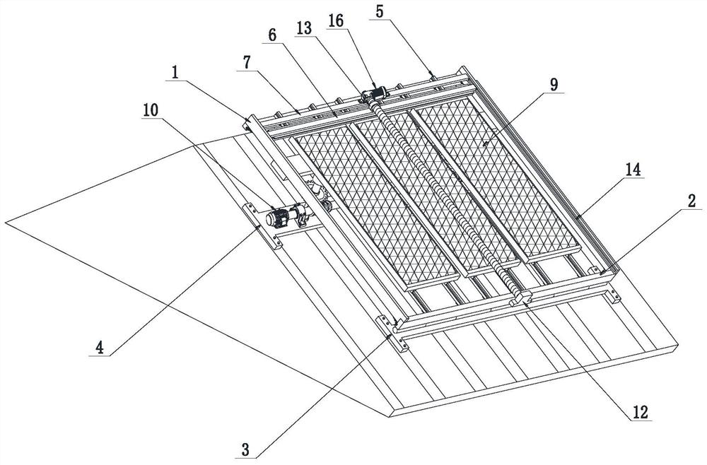
The invention relates to the technical field of photovoltaic panels, and particularly discloses an intelligent roof photovoltaic panel and a mounting structure thereof. The intelligent roof photovoltaic panel comprises two longitudinal plates and two transverse plates, the two longitudinal plates and the two transverse plates are correspondingly arranged in a rectangular shape, and a plurality ofmounting rods are mounted between the two transverse plates at equal intervals; photovoltaic panels are mounted at the upper ends of the mounting rods and located on the inner sides of the transverseplates, a first mounting plate is arranged on the lower surface of one transverse plate, a connecting plate is mounted on the lower surface of the other transverse plate and located on one side of thelongitudinal plate, and the mounting structure further comprises a lifting mechanism, a cleaning mechanism and a connecting mechanism. Compared with the prior art, the photovoltaic panels and the mounting structure are designed to be in clamping connection from traditional bolt connection, mounting is rapid, maintenance is convenient, the multiple photovoltaic panels are integrally controlled, auser can automatically and uniformly adjust the photovoltaic panels conveniently, the long-term use quality of the photovoltaic panels is guaranteed, the service life of the photovoltaic panels is prolonged, and the maintenance efficiency of the photovoltaic panels is improved.

Description

technical field [0001] The invention relates to the technical field of photovoltaic panels, in particular to an intelligent roof photovoltaic panel and its installation structure. Background technique [0002] In recent years, all countries are actively promoting the application of renewable energy, and the development of the photovoltaic industry is very rapid. The photovoltaic system can be installed on a large scale on the ground to become a photovoltaic power station, or it can be placed on the roof or outer wall of a building to form a photovoltaic system. Building integration, with the enhancement of people's awareness of environmental protection, at this stage, the country vigorously advocates the use of photovoltaic power generation and takes the road of new energy. For this reason, many areas in the west have established new energy demonstration areas, laying photovoltaic panels on the sunny side of the roof of every household. Solve the problem of power shortage th...

Claims


Application Information

Patent Timeline
IPC IPC(8): H02S20/30H02S20/23F24S25/61H02S40/10H02S40/12
CPCH02S20/30H02S20/23F24S25/61H02S40/10H02S40/12Y02E10/47Y02E10/50Y02B10/10Y02B10/20
Inventor 王姜愉
Owner 宁波锦锐能源科技有限公司
Learn More