Supercharge Your Innovation With Domain-Expert AI Agents!

A display device for internal parts of a mechanical lockbox

A technology for internal parts and display devices, applied in display hangers, home appliances, display shelves, etc., can solve the problems of inconvenient observation, low practicability, and low stability, and achieve easy observation, high practicability, and high stability. Effect

Active Publication Date: 2021-12-10
衡阳市慧育科技有限公司
View PDF12 Cites 0 Cited by
  • Summary
  • Abstract
  • Description
  • Claims
  • Application Information

AI Technical Summary

Problems solved by technology

[0004] During its use, when there are many visitors, the visitors only observe at a fixed position, and the parts need to be displayed at more angles, which is not convenient for visitors to observe, with low stability and low practicability

Method used


Image

  • A display device for internal parts of a mechanical lockbox
  • A display device for internal parts of a mechanical lockbox
  • A display device for internal parts of a mechanical lockbox

Examples


Embodiment 1

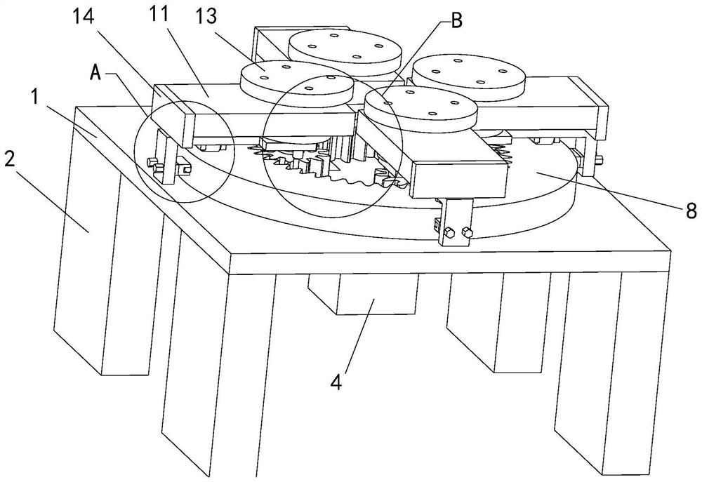
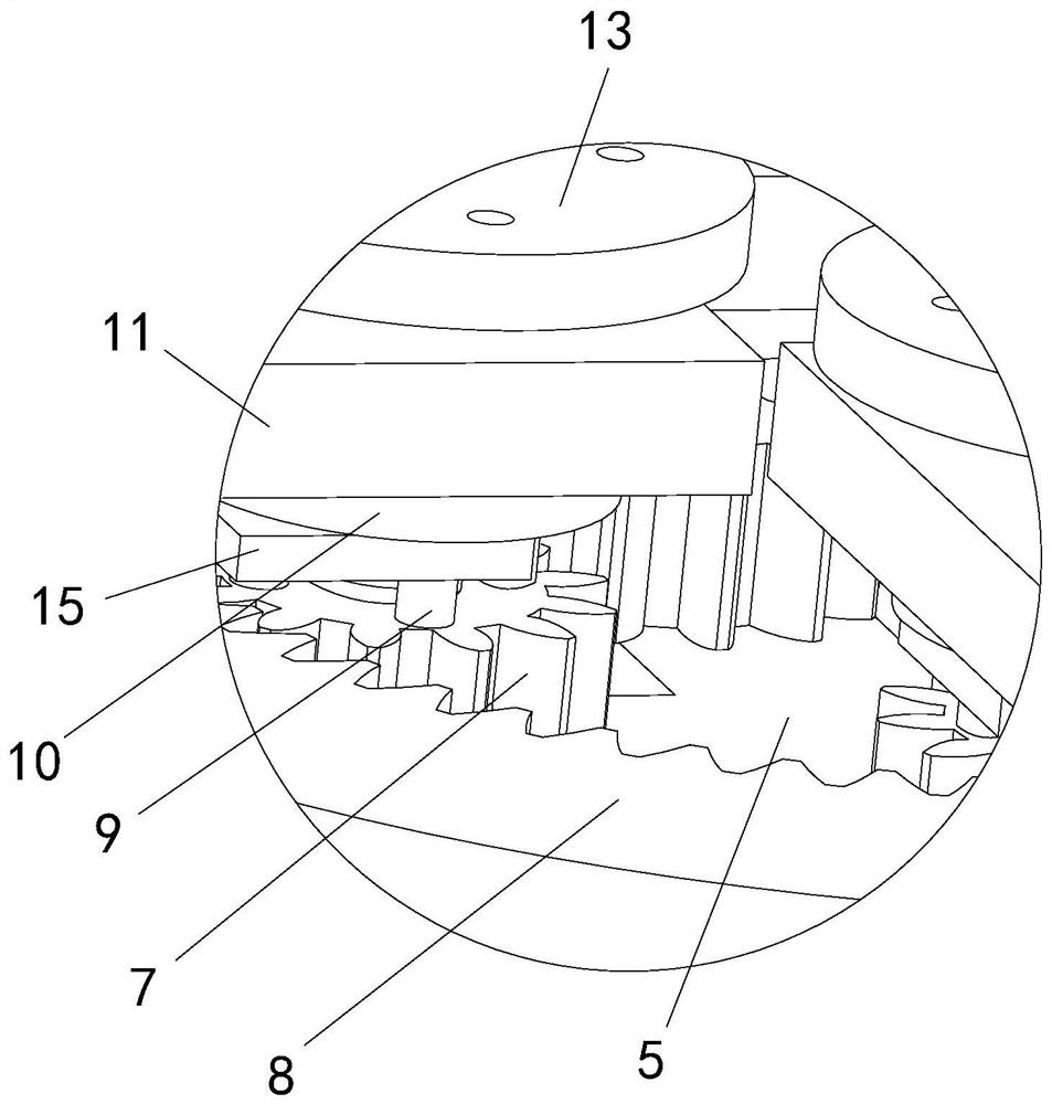
[0034] see Figure 1-12 , a display device for internal parts of a mechanical lockbox, comprising a support plate 1, support legs 2 are fixedly connected to the four corners of the bottom end of the support plate 1, a relief hole is provided in the middle of the support plate 1, and the support plate 1 The middle part of the bottom end of the board 1 is fixedly connected with an adapter plate 3, the bottom end of the adapter plate 3 is equipped with a servo motor 4, and the output shaft end of the servo motor 4 is fixedly connected with a toggle plate 5, and the toggle plate 5 The plate 5 is in the shape of a "ten", and the top front part, the top rear part, the top left part and the top right part of the toggle plate 5 are fixedly connected with support shafts 6, and the peripheral outer walls of each support shaft 6 are fitted Gear 7 is arranged, and the top of each described support shaft 6 is fixedly connected with the limit boss 28, and the bottom end of each described li...

Embodiment 2

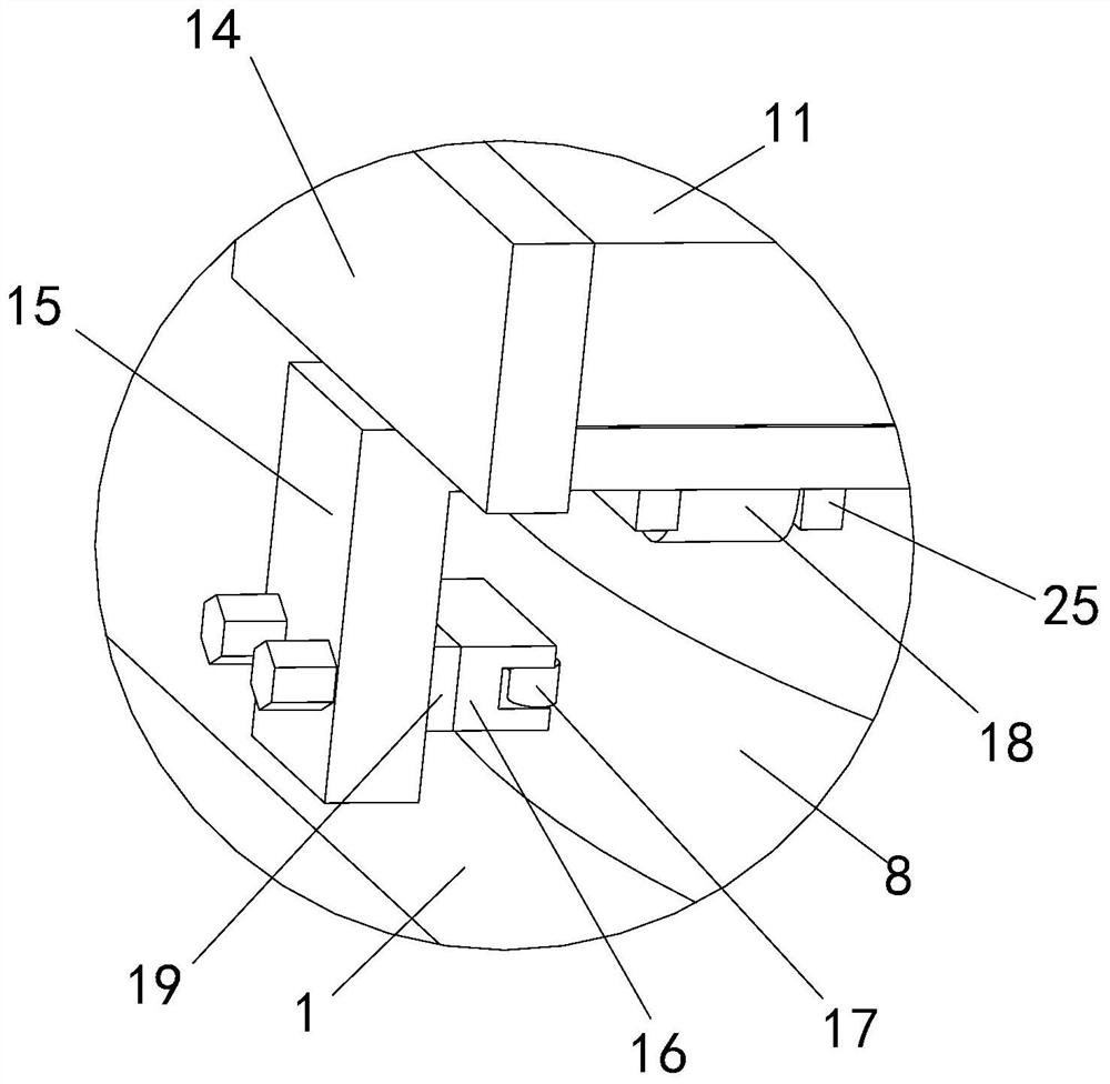
[0038] see Figure 1-12 , a display device for internal parts of a mechanical lockbox, the opposite ends of the supporting plate 16 and the receiving plate 15 are connected by screws, and the relative middle areas of the supporting plate 16 and the receiving plate 15 are provided with adjusting gaskets 19, The middle part of the adjusting gasket 19 is provided with a via hole, and the top of the receiving plate 15 is fixedly connected with two fixing blocks 20, and the two ends of the fixing blocks 20 are provided with "T" grooves, each of the "T" "The block 21 is arranged in the groove, and the top of each block 21 is fixedly connected with an adjustment screw 22, and the upper side of each fixed block 20 is provided with a shelf plate 23, and each of the adjustment screws 22 The upper part is connected with the middle part of each corresponding shelf plate 23 by threads, and one end of each said shelf plate 23 is all fixedly connected with a connecting shaft 24, and the insi...


PUM


Abstract

The invention relates to the technical field of mechanical lockbox display, in particular to a display device for internal parts of a mechanical lockbox, including a support plate, a support leg, an adapter plate, a servo motor, a toggle plate, a support shaft and a gear, and the middle part of the top end of the support plate is fixedly connected There is a gear ring, the gear ring meshes with each gear, the top of each gear is fixedly connected with a plurality of transfer shafts, the upper side of each gear is provided with a disc, and the bottom of the disc is connected to the bottom of each corresponding transfer shaft. The ends are fixedly connected, the upper part of each disc is provided with a horizontal plate, and the bottom of each horizontal plate is provided with a positioning hole corresponding to the disc, the outer wall of the disc is in contact with the inner wall of each corresponding positioning hole, and each horizontal plate The end far away from the middle of the gear ring is equipped with a limit device, the top of the disc is fixedly connected with a heightening shaft, the top of the heightening shaft passes through the horizontal plate from the inside of the positioning hole, and the top of each heightening shaft is fixedly connected with a mounting plate; It is convenient for visitors to observe, has high stability and high practicability.

Description

technical field [0001] The invention relates to the technical field of mechanical lockbox display, in particular to a display device for internal parts of a mechanical lockbox. Background technique [0002] The mechanical combination box is a device that uses mechanical principles to keep the box secret. In the process of displaying in the exhibition and in the factory, it is necessary to display the structure of the internal parts of the box. [0003] After searching, the patent publication number is CN211748422U, which discloses a display device for mechanical parts of different shapes, including a turret, a guide rail and a base. The rotating shaft and the turret are connected by rotation. The tray hangers are evenly installed on the turntable. There are six tray hangers. The display frame is set on the end of the six tray hangers away from the turntable. The upper right of the turret is equipped with a transmission box. , There is a guide rail on the upper position of t...

Claims


Application Information

Patent Timeline
Patent Type & Authority Patents(China)
IPC IPC(8): A47F5/00A47F5/025A47F7/00
CPCA47F5/00A47F5/025A47F7/00
Inventor 邓利云陈志强周颜芝罗双印
Owner 衡阳市慧育科技有限公司
Features
  • R&D
  • Intellectual Property
  • Life Sciences
  • Materials
  • Tech Scout
  • Unparalleled Data Quality
  • Higher Quality Content
  • 60% Fewer Hallucinations
Learn More