
Heat shield forming die structure

A technology for forming molds and heat shields, which is applied in the field of heat shield forming mold structures, can solve problems such as troublesome, laborious, and heat shield forming molds that cannot be used for stamping stretched plates, and achieves the effect of convenient stamping

Inactive Publication Date: 2021-03-12
十堰市雄振汽车零部件有限公司
View PDF0 Cites 0 Cited by
  • Summary
  • Abstract
  • Description
  • Claims
  • Application Information

AI Technical Summary

Problems solved by technology

[0005] In order to solve the above-mentioned technical problems, the present invention provides a heat shield molding die structure to solve the need to punch mounting holes of different sizes when punching the existing heat shield, and to replace different stamping die shapes, which is troublesome. The installation position is different, do not adjust after the mold is installed, it is more laborious, the ordinary heat shield forming mold cannot be used for stamping the processed parts with thin tensile plate thickness

Method used


Image

  • Heat shield forming die structure
  • Heat shield forming die structure
  • Heat shield forming die structure

Examples


Embodiment

[0027] as attached figure 1 to attach Figure 6 Shown:

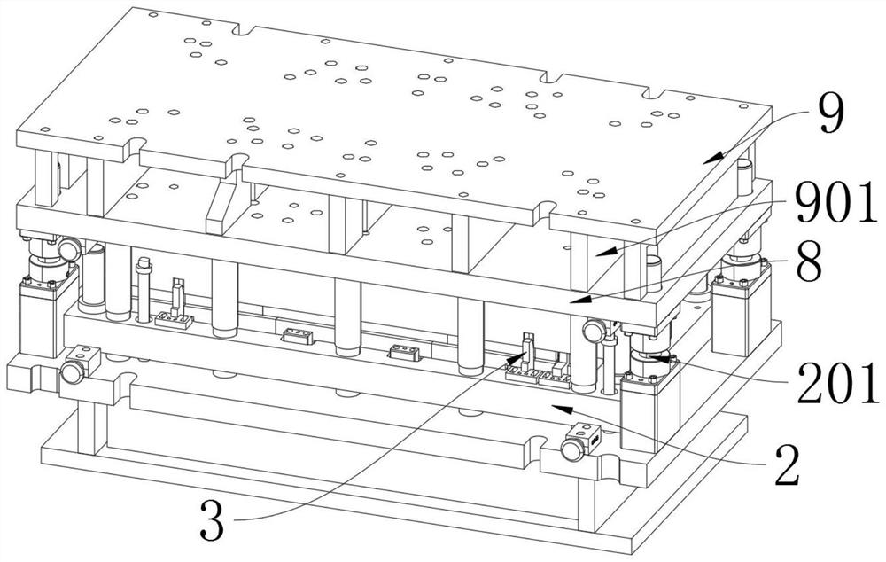
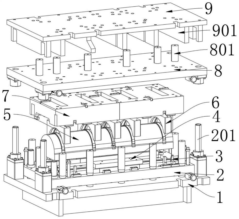
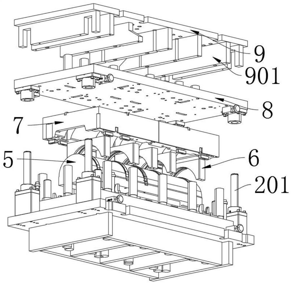
[0028] The invention provides a heat shield forming mold structure, which includes a base 1; a tray 2 is fixed on the base 1 by bolts, and a group of circular support rods are installed on the tray 2, and threaded holes are provided on the support rods; There is a set of sliding blocks 4 with threaded holes, and six sets of pipe positions 3 are installed on the tray 2, and a lower mold shape 5 is clamped on the tray 2; a stamping block 6 is clamped above the lower mold shape 5, and the stamping The block 6 is fixed on the upper mold shape 7 by bolts; the upper mold shape 7 is fixed with a connecting plate 8 by bolts, and the connecting plate 8 includes a connecting column 801, and the connecting column 801 is fixed with a top plate 9 by bolts; the top plate 9 includes There are supporting blocks 901, and two rectangular slots are opened on the supporting blocks 901 at the left and right ends;

[0029] Wherein, the pip...


PUM


Abstract

The invention provides a heat shield forming die structure. The heat shield forming die structure comprises a base. A tray is fixed to the base through bolts. A set of circular supporting rods are installed on the tray. Threaded holes are formed in the supporting rods. A set of sliding blocks with threaded holes are installed on the tray. Six sets of pipe positions are installed on the tray. A lower die body is clamped to the tray. A stamping block is clamped to the upper portion of the lower die body and fixed to an upper die body through bolts. A positioning base is arranged on the tray, andtherefore the lower die body and the upper die body can be conveniently aligned. The sliding blocks can be conveniently adjusted through sliding grooves formed in the tray. An insert is arranged on the lower die body, and therefore the insert is replaced to continue to stamp heat shields when different heat shields are stamped. The heat shield stamping effect is achieved through the stamping block arranged on the upper die body. All stamping parts are shared, adjustment is not needed when heat shield holes of different sizes are stamped, and the stamping is convenient.

Description

technical field [0001] The invention belongs to the technical field of molding dies, and more specifically relates to a molding die structure for a heat shield. Background technique [0002] The forming mold is also called the mold. It is a mold made in proportion to the shape and structure of the object. The material is made into a tool of a certain shape by pressing or pouring. It is generally used for plastic processing. It needs to pass through the mold during the production of heat shields. Stamping. [0003] Based on the above, when the existing heat shield is stamped, it is necessary to punch different sizes of mounting holes, and it is necessary to replace different stamping die shapes, which is troublesome. Because the installation positions of the dies are different, it is laborious to adjust the dies after they are installed. Ordinary The heat shield forming die cannot be used for stamping and drawing thinner workpieces. [0004] Therefore, in view of this, the ...

Claims


Application Information

Patent Timeline
Patent Type & Authority Applications(China)
IPC IPC(8): B21D28/34B21D37/04
CPCB21D28/34B21D37/04
Inventor 戢运福戢运宏张学清李河湖闫根生陈飞
Owner 十堰市雄振汽车零部件有限公司
Learn More