Chopping board slotting and forming equipment for kitchen

A technology for forming equipment and cutting boards, which is applied in the field of kitchen cutting board slotting and forming equipment, which can solve the problems of many operations, inability to achieve precise slotting, low work efficiency, etc., and achieve the effect of achieving the effect of rotation

Active Publication Date: 2021-03-12
NANJING YUZHI INTELLIGENT TECH CO LTD
View PDF10 Cites 7 Cited by
  • Summary
  • Abstract
  • Description
  • Claims
  • Application Information

AI Technical Summary

Problems solved by technology

[0005] In order to overcome the shortcomings of traditional slotting methods such as many operations, low work efficiency, and inability to achieve precise slotting, the technical problem to be solved is to provide a cutting board for kitchen with simple operation, high work efficiency, and accurate slotting. equipment

Method used


Image

  • Chopping board slotting and forming equipment for kitchen
  • Chopping board slotting and forming equipment for kitchen
  • Chopping board slotting and forming equipment for kitchen

Examples


Embodiment 1

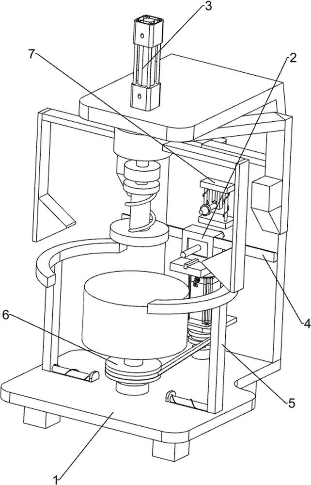
[0065] A cutting board slotting and forming equipment for kitchen, such as figure 1 As shown, it includes a base 1 , a slotting mechanism 2 and a clamping mechanism 3 . The slotting mechanism 2 is provided in the middle of the upper front wall of the base 1 , and the clamping mechanism 3 is provided on the base 1 .

[0066] When people want to slot the chopping board, they can use this kitchen chopping board slotting forming equipment. First, the user places the chopping board that needs to be slotted in the clamping mechanism 3, starts the slotting mechanism 2, and performs the cutting process on the chopping board. Grooving.

Embodiment 2

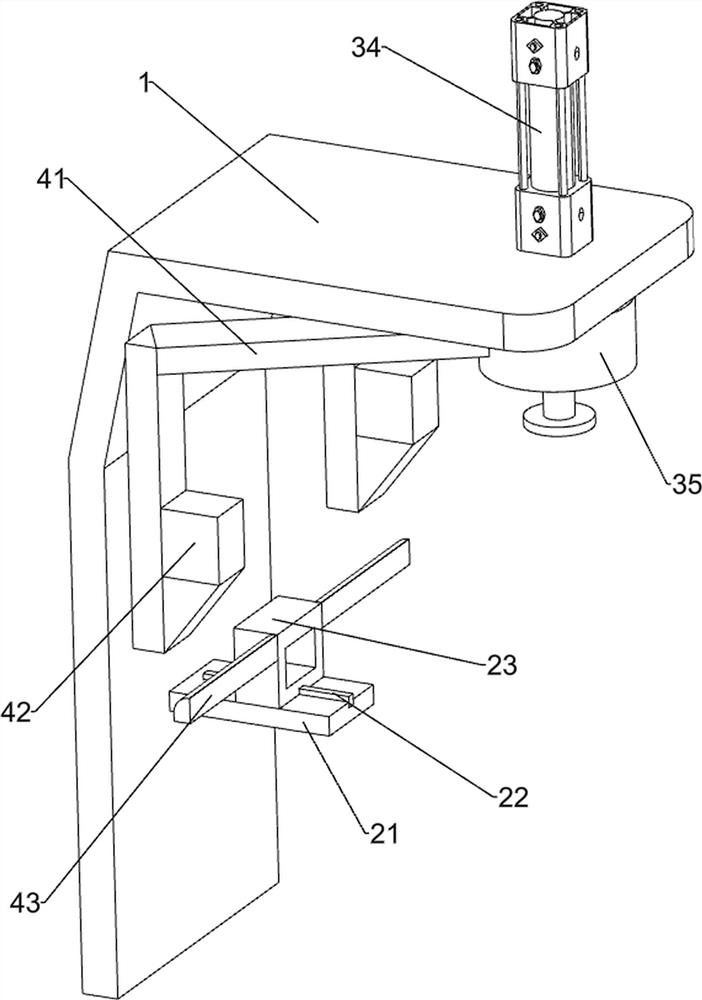
[0068] On the basis of Example 1, such as figure 2 with image 3As shown, the slotting mechanism 2 includes a first support frame 21, a slider 22, a second support frame 23, a rotary cutter 24 and a first telescopic assembly 25, and the middle part of the upper front wall of the base 1 is provided with a first support frame 21, The middle of the first support frame 21 top is provided with a slide block 22, the slide block 22 top sliding type is provided with a second support frame 23, the front side of the second support frame 23 inner wall is rotatably provided with a rotary cutter 24, and the second support frame 23 rear side A first telescopic assembly 25 is provided.

[0069] The user starts the rotary cutter 24, pushes the second support frame 23 forward, and the first telescopic assembly 25 stretches to slot the cutting board to realize the slotting effect. After the slotting is completed, the second support frame 23 is pushed backward, The first telescopic assembly 2...

Embodiment 3

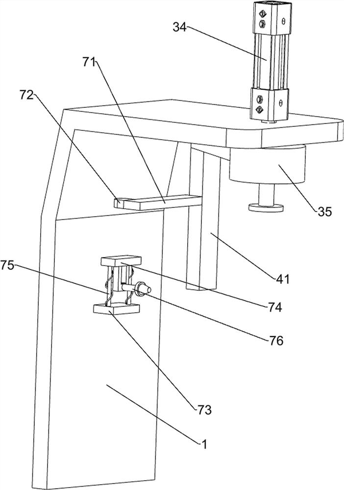
[0073] On the basis of Example 2, such as Figure 4-Figure 7 As shown, a moving mechanism 4 is also included. The rear side of the push plate 35 is provided with a moving mechanism 4. The moving mechanism 4 includes a second connecting rod 41, a first wedge block 42 and an arc block 43. The rear side of the push plate 35 is provided with a The two second connecting rods 41 are provided with first wedge-shaped blocks 42 on the lower front sides of the two second connecting rods 41 , and arc-shaped blocks 43 are provided on the left and right sides of the second support frame 23 .

[0074] When the push plate 35 moves downward, it drives the second connecting rod 41 to move downward, and then drives the first wedge block 42 to move downward. The first wedge block 42 contacts the arc block 43, thereby driving the arc block 43 to move downward. Move forward, and then drive the second support frame 23 to move forward to realize the moving effect. When the push plate 35 moves upward...


PUM


Abstract

The invention relates to slotting equipment, in particular to chopping board slotting and forming equipment for a kitchen. The chopping board slotting and forming equipment for the kitchen is easy tooperate, high in working efficiency and capable of achieving accurate slotting. The chopping board slotting and forming equipment for a kitchen comprises a base and a clamping mechanism, and a slotting mechanism is arranged in the middle of the upper front wall of the base. and the clamping mechanism is arranged on the base. By starting a rotating cutter, a second supporting frame is pushed forwards, a first telescopic assembly stretches to slot chopping board, and the slotting effect is achieved; and the telescopic rod of an air cylinder extends downwards to drive the push plate to move downwards, then a first connecting rod is driven to move downwards, a second telescopic assembly is compressed, a first pressing plate is driven to move downwards, the first pressing plate makes contact with the chopping board, and the clamping effect is achieved.

Description

technical field [0001] The invention relates to a grooving device, in particular to a grooving and forming device for cutting boards used in kitchens. Background technique [0002] The traditional cutting board slotting method is to manually place the cutting board on the slotting equipment, make the cutting board contact with the slotting drill bit, then turn the cutting board, and then slot. During this process, there are many operations, low work efficiency, and Precise grooving cannot be achieved. [0003] Patent application CN111605005A, with a publication date of 20200901, discloses a cutting board slotting device, including a workbench, a motor, a drill, a clamping assembly, a lower pressing plate, a transmission assembly, and a fixing column. By placing the cutting board on the workbench, The clamping component clamps the cutting board, and then starts the motor, and the output shaft of the motor drives the transmission component to rotate, thereby driving the drill...

Claims


Application Information

Patent Timeline
Patent Type & Authority Applications(China)
IPC IPC(8): B27F5/02B27C5/02B27C5/06B27G3/00
CPCB27F5/02B27C5/02B27C5/06B27G3/00
Inventor 叶建新
Owner NANJING YUZHI INTELLIGENT TECH CO LTD
Why Eureka
Try Eureka