A kind of kitchen cutting board slotting forming equipment
A technology for forming equipment and cutting boards, which is applied in the field of kitchen cutting board slotting and forming equipment, which can solve the problems of many operations, inability to achieve precise slotting, low work efficiency, etc., and achieve the effect of achieving the effect of rotation
- Summary
- Abstract
- Description
- Claims
- Application Information
AI Technical Summary
Problems solved by technology
Method used
Image
Examples
Embodiment 1
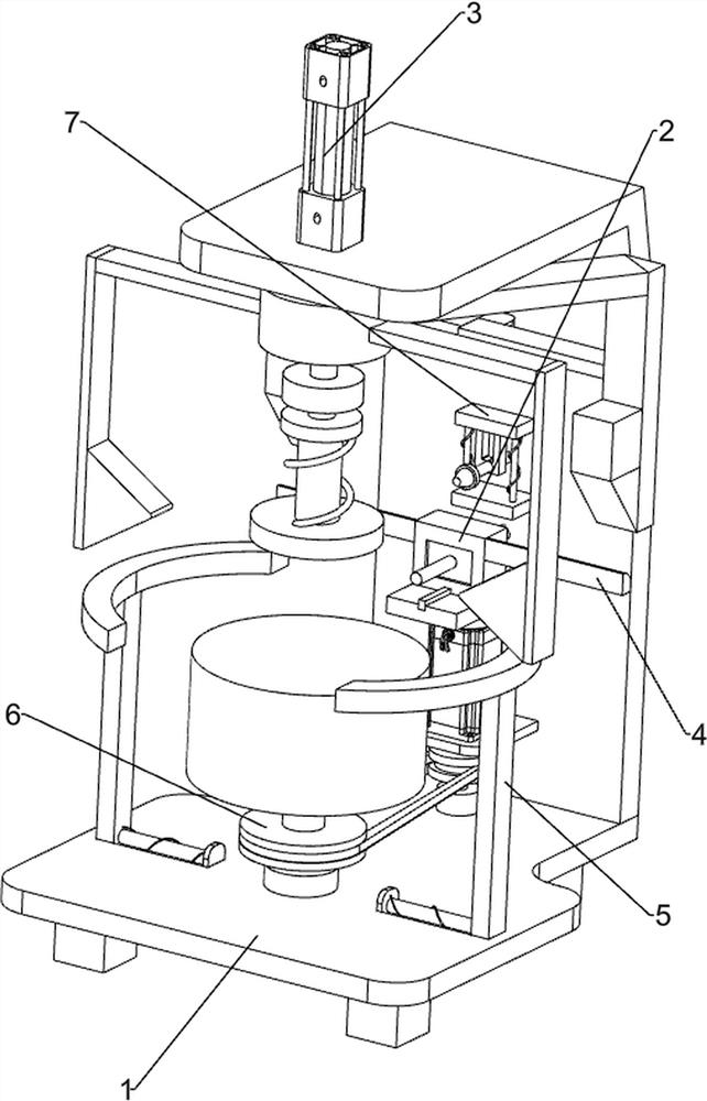
[0065] A kitchen cutting board slotting and forming equipment, such as figure 1 As shown, it includes a base 1 , a slotting mechanism 2 and a clamping mechanism 3 , a slotting mechanism 2 is arranged in the middle of the front wall of the base 1 , and a clamping mechanism 3 is arranged on the base 1 .
[0066] When people want to groov the cutting board, they can use this kitchen cutting board grooving forming equipment. First, the user places the cutting board that needs to be grooved in the clamping mechanism 3, activates the grooving mechanism 2, and makes the cutting board. Slotted.
Embodiment 2
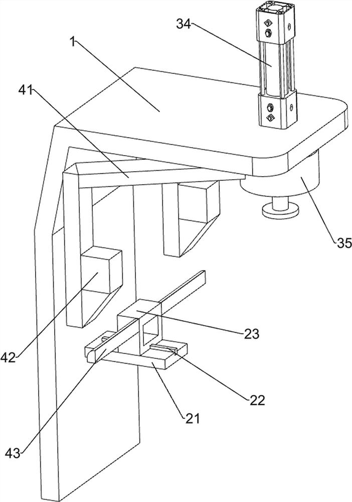
[0068] On the basis of Example 1, as figure 2 and image 3As shown, the slotting mechanism 2 includes a first support frame 21, a sliding block 22, a second support frame 23, a rotating cutter 24 and a first telescopic assembly 25, and a first support frame 21 is provided in the middle of the upper front wall of the base 1, A sliding block 22 is provided in the middle of the top of the first supporting frame 21 , a second supporting frame 23 is slidably provided on the top of the sliding block 22 , a rotary cutter 24 is rotatably provided on the front side of the inner wall of the second supporting frame 23 , and the rear side of the second supporting frame 23 A first telescopic assembly 25 is provided.
[0069] The user starts the rotating tool 24, pushes the second support frame 23 forward, the first telescopic assembly 25 stretches, and grooves the cutting board to achieve the groove effect. After the groove is completed, the second support frame 23 is pushed backward, T...
Embodiment 3
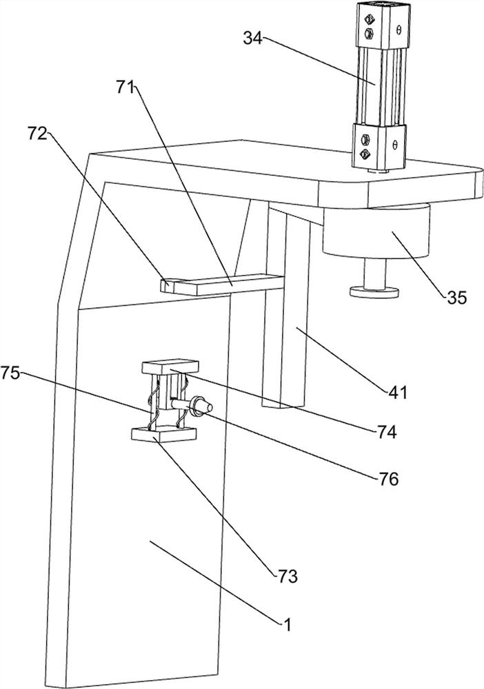
[0073] On the basis of Example 2, as Figure 4-Figure 7 As shown, it also includes a moving mechanism 4, the rear side of the push plate 35 is provided with a moving mechanism 4, and the moving mechanism 4 includes a second connecting rod 41, a first wedge block 42 and an arc block 43, and the rear side of the push plate 35 is provided with The two second connecting rods 41 are provided with a first wedge-shaped block 42 at the lower part of the front side of the two second connecting rods 41 , and the left and right sides of the second support frame 23 are provided with arc-shaped blocks 43 .
[0074] When the push plate 35 moves downward, it drives the second connecting rod 41 to move downward, which in turn drives the first wedge block 42 to move downward. The first wedge block 42 contacts the arc block 43 and drives the arc block 43 to move downward. When the push plate 35 moves upward, it drives the second connecting rod 41 to move upward, which in turn drives the first w...
PUM
 Abstract
Description
Claims
Application Information
 - R&D
- Intellectual Property
- Life Sciences
- Materials
- Tech Scout
- Unparalleled Data Quality
- Higher Quality Content
- 60% Fewer Hallucinations
Browse by: Latest US Patents, China's latest patents, Technical Efficacy Thesaurus, Application Domain, Technology Topic, Popular Technical Reports.
© 2025 PatSnap. All rights reserved.Legal|Privacy policy|Modern Slavery Act Transparency Statement|Sitemap|About US| Contact US: help@patsnap.com


