Injection molding structure of a tee pipe fitting

A technology of three-way pipe fittings and injection molding, which is applied to tubular articles, household components, household appliances, etc., can solve the problems of weight change and production cost increase of three-way pipe fittings, and achieve the effect of improving hydraulic performance and avoiding welding marks.

Active Publication Date: 2022-05-24
HESHAN LESSO IND DEV
View PDF4 Cites 0 Cited by
  • Summary
  • Abstract
  • Description
  • Claims
  • Application Information

AI Technical Summary

Problems solved by technology

[0004] In the above technical solution, the performance structure of the tee fitting is improved through the function of the insert, but at the same time, additional parts need to be added to the tee, resulting in an increase in production cost and a change in the weight of the tee fitting
In addition, in the scheme, injection molding is carried out through multiple through holes, which is easy to produce multiple weld lines

Method used


Image

  • Injection molding structure of a tee pipe fitting
  • Injection molding structure of a tee pipe fitting

Examples


Embodiment 1

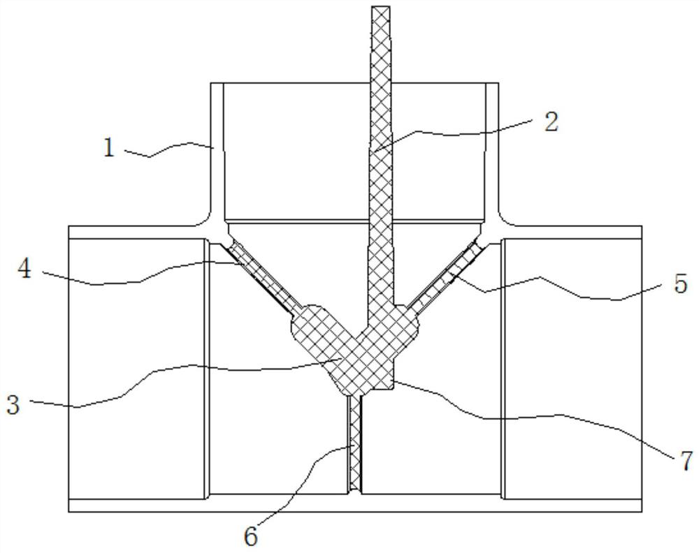
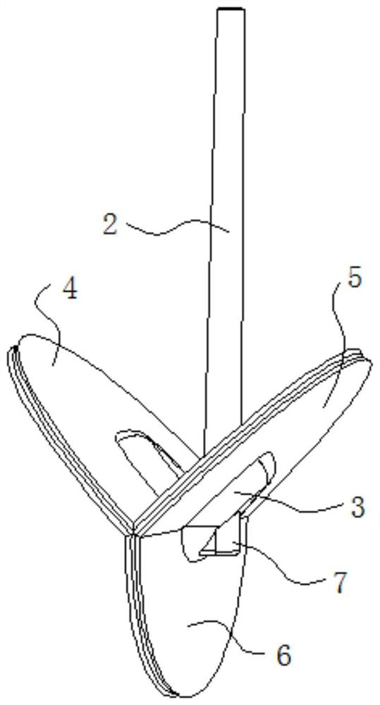
[0021] as Figure 1-2An embodiment of an injection molding structure shown as a three-way pipe fitting fixture, comprising a cavity 1 and a runner disposed in the cavity 1; the runner comprises a main gate 2, a storage portion 3 connecting the main gate 2 and a connected storage portion 3 and a distribution along the 3 circumferences of the storage portion 4, the second gate portion 5 and the third gate portion 6, the first gate portion 4, the second gate portion 5 and the third gate portion 6 are all connected to the cavity 1.

[0022] Among them, the first gate 4, the second gate 5 and the third gate 6 are Y-shaped. From the structure of the three-way pipe fittings, the connection of the tee pipe fittings is divided into three parts, namely the lower end part, the upper left part and the upper right part of the tee pipe fittings, through the Y-shaped distribution setting of the three gate parts, each gate part is injected into one of the parts, so that the melt flows in three dir...

Embodiment 2

[0029] Another embodiment of a fixture for the injection molding structure of a three-way pipe fitting, the difference with Example 1 is that the storage portion 3 is Y-type, the first gate portion 4, the second gate portion 5 and the third gate portion 6 are connected to the end angle of the storage portion 3, respectively, to ensure that the storage portion 3 is filled, the melt can be evenly dispersed to the three gates. There is a cold feed well 7 between the main gate 2 and the storage section 3. When the plastic melt passes through the main gate 2 runner, the front end of the cold material is stored in the cold material well 7 to avoid the cold material from affecting the effect of injection molding.

[0030] The remaining features and working principles of the present embodiment are consistent with Example 1.


PUM


Abstract

The invention relates to the field of pipe injection molds, more specifically, to an injection molding structure of a three-way pipe fitting, including a cavity and a flow channel arranged in the cavity; the flow channel includes a main gate and a storage part connected to the main gate And the first gate part, the second gate part and the third gate part which are connected to the material storage part and distributed along the circumferential direction of the material storage part, the first gate part, the second gate part and the third gate part are connected to the cavity. The runner injects melt into three directions of the cavity through the three gates at the same time, and the melt flows in three different directions, so that the melts do not meet, avoiding the generation of weld lines, and improving the hydraulic performance of the product .

Description

Technical field [0001] The present invention relates to the field of tube injection molds, more particularly, to a three-way pipe fitting injection molding structure. Background [0002] At present, the three-way pipe fittings on the market are generally single-point and double-point glue, the product has more problems with weld marks, and the temperature difference between the temperature of the inlet and other parts of the cavity is larger, and the shrinkage stress near the glue inlet after the product is produced after injection molding, affecting the product performance structure, and the position of the inlet is often cracked by hydraulic detection, and the crack at the weld line is broken. [0003] The patent document with the publication number "CN209705501U" discloses a kind of insert with through-hole secondary molding full plastic tee, including inserts, textures, body and through holes, the inserts are provided with through holes, the inner and outer surfaces of the in...

Claims


Application Information

Patent Timeline
Patent Type & Authority Patents(China)
IPC IPC(8): B29C45/27B29L23/00B29L31/24
CPCB29C45/27B29L2023/00B29L2031/246
Inventor 谭建志
Owner HESHAN LESSO IND DEV
Why Eureka
Try Eureka