
Invisible lamp based on convex lens

A convex lens and invisible technology, which is applied in the parts of lighting devices, semiconductor devices of light-emitting elements, lighting and heating equipment, etc., can solve the problems of unsightly vision, single light performance, and insufficient brightness, etc., and achieve a wide range of applications. The effect of wide scene and good lighting effect

Inactive Publication Date: 2021-03-12
内蒙古旭坤电子科技有限公司
View PDF0 Cites 0 Cited by
  • Summary
  • Abstract
  • Description
  • Claims
  • Application Information

AI Technical Summary

Problems solved by technology

[0002] Most of the existing chandelier manufacturers use a combination of light bulbs and transparent glass lampshades for the sake of beauty. This kind of lamp can still see the lamp, lamp body and other components visually, especially when the light is turned off, the visual appearance is still not beautiful enough, and it has not been realized. Visually, the lamp is invisible. Some manufacturers replace the transparent glass lampshade with a frosted glass lampshade. Although the bulb and the fixing parts cannot be seen directly, the frosted glass lampshade has poor permeability and insufficient aesthetics. The convex lens is Made according to the principle of refraction of light, according to Figure 4 The property of the invisible edge of the convex lens, from the spherical side of the convex lens, only the magnified virtual image in the area A that is close to the bottom plane of the convex lens can be seen, but the ring area B that is close to the bottom plane of the convex lens cannot be observed visually
[0003] The light of the existing lamps is single, lacks the sense of technology, innovation and novelty, and is not suitable for personalized lighting and brightening occasions, and some lamps will block part of the light due to the existence of the top plate, resulting in insufficient brightness, and the light cannot Very good divergence, so now we propose an invisible light based on a convex lens

Method used


Image

  • Invisible lamp based on convex lens
  • Invisible lamp based on convex lens
  • Invisible lamp based on convex lens

Examples


Embodiment 1

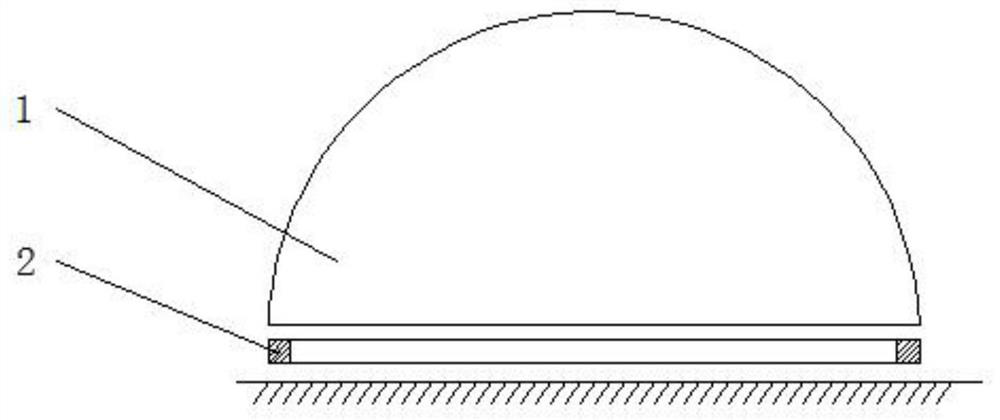
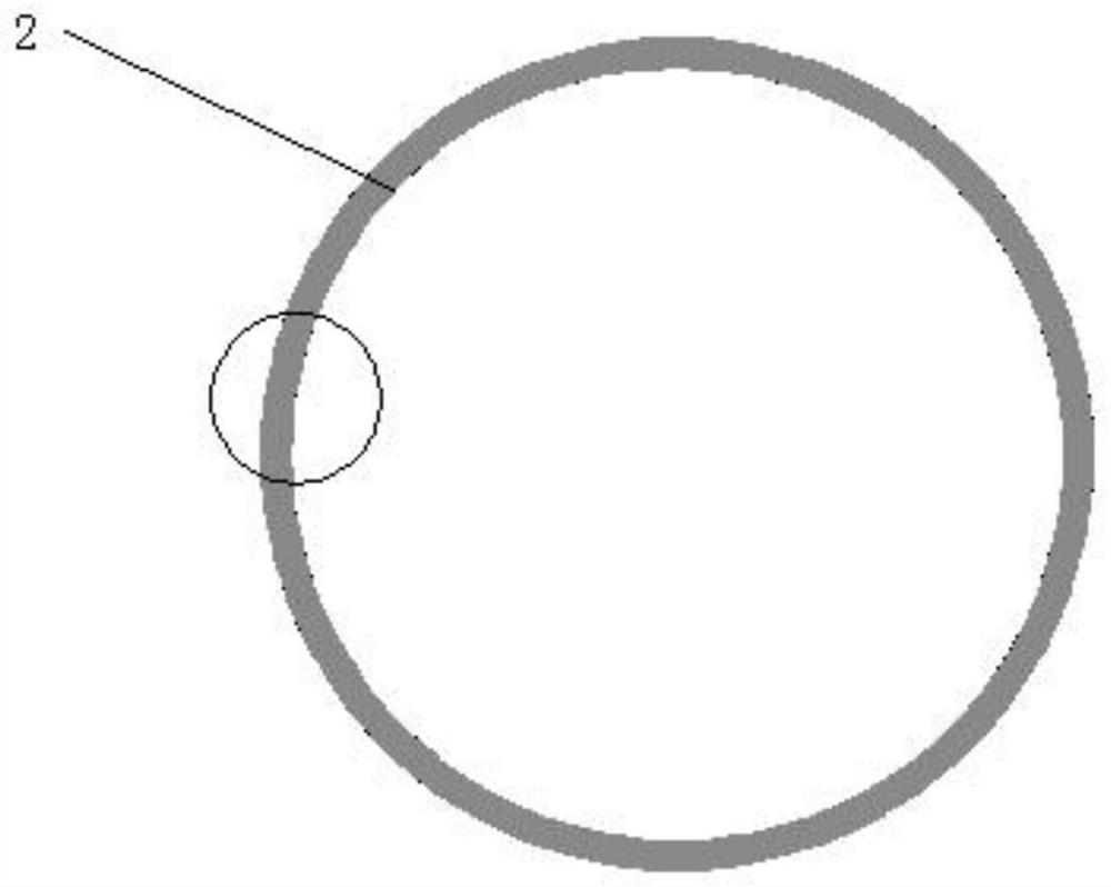
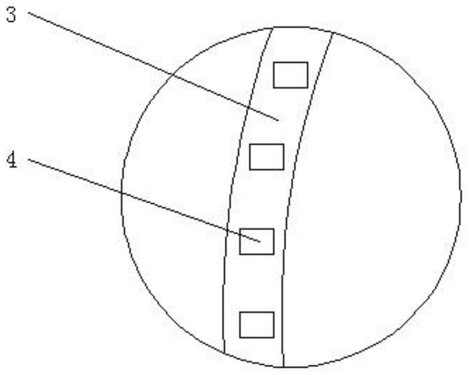
[0025] refer to figure 1 , including the lamp body 2, the lamp body 2 is in the form of a hollow ring, the lamp body 2 includes a hollow ring plate 3, the hollow ring plate 3 is made of ultra-thin glass material, and several light-emitting units are arranged in a ring on the upper side of the hollow ring plate 3 4. A convex lens 1 is provided on the upper side of the lamp body 2 .

[0026] In the present invention, several light-emitting units 4 adopt conventional lamp beads, and the connection mode between several light-emitting units 4 is one or a combination of parallel connection and series connection, so that the effect is changed synchronously as a whole, and the light-emitting units 4 pass UV glue It is connected with the hollow ring plate 3, the convex lens 1 is a plane convex lens, and the cross section of the convex lens 1 is semi-elliptical, and the side of the lamp body 2 away from the convex lens 1 is fixed to the wall or a plane carrier, and only the spherical s...

Embodiment 2

[0028] refer to figure 1 , including the lamp body 2, the lamp body 2 is in the form of a hollow ring, the lamp body 2 includes a hollow ring plate 3, the hollow ring plate 3 is made of ultra-thin glass material, and several light-emitting units are arranged in a ring on the upper side of the hollow ring plate 3 4. A convex lens 1 is provided on the upper side of the lamp body 2 .

[0029] In the present invention, the light-emitting unit 4 is a built-in IC integrated lamp bead, and the built-in IC integrated lamp bead is cascaded, in addition to realizing the overall change, it can also realize special pattern changes such as dazzling colors, moving, flowing water, tail sweeping, accumulation, and meteor shower. , the built-in IC integrated lamp bead is an intelligent external control LED light source that integrates the control circuit and the light-emitting circuit. Its appearance is the same as that of an LED lamp bead in the same package. The intelligent digital interfa...

Embodiment 3

[0031] refer to Figure 5 , an invisible lamp based on a convex lens, including a lamp body 2, the lamp body 2 is a hollow ring, the lamp body 2 includes a hollow ring plate 3, the hollow ring plate 3 is made of ultra-thin glass material, and the upper and lower sides of the hollow ring plate 3 Several light-emitting units 4 are evenly distributed in a ring shape, and convex lenses 1 are symmetrically arranged on the upper and lower sides of the lamp body 2 .

[0032] In the present invention, several light-emitting units 4 adopt conventional lamp beads, and the connection mode between several light-emitting units 4 is one or a combination of parallel connection and series connection, so that the effect is changed synchronously as a whole, and the light-emitting units 4 pass UV glue Connected with the hollow ring plate 3, the convex lens 1 is a planar convex lens, and the cross-section of the convex lens 1 is semi-elliptical. From the spherical side of the convex lens 1, only ...


PUM


Abstract

The invention discloses an invisible lamp based on a convex lens. The invisible lamp based on the convex lens comprises a lamp body, the lamp body is in a hollow circular ring shape and comprises a hollow circular ring plate, the hollow circular ring plate is made of an ultrathin glass material, a plurality of light emitting units are annularly distributed on the upper side of the hollow circularring plate, and the convex lens is arranged on the upper side of the lamp body. A plurality of light-emitting units adopt conventional lamp beads, and the plurality of light-emitting units are connected in parallel or in series or in a combination of parallel connection and series connection, so that the visual invisible lamp is achieved through the convex lens and the lamp body, the sense of science and technology and the novelty are more outstanding, and the invisible lamp is suitable for personalized lighting and brightening occasions and is wide in application scene.

Description

technical field [0001] The invention relates to the technical field of invisible lamps, in particular to an invisible lamp based on a convex lens. Background technique [0002] Most of the existing chandelier manufacturers use a combination of light bulbs and transparent glass lampshades for the sake of beauty. This kind of lamp can still see the lamp, lamp body and other components visually, especially when the light is turned off, the visual appearance is still not beautiful enough, and it has not been realized. Visually, the lamp is invisible. Some manufacturers replace the transparent glass lampshade with a frosted glass lampshade. Although the bulb and the fixing parts cannot be seen directly, the frosted glass lampshade has poor permeability and insufficient aesthetics. The convex lens is Made according to the principle of refraction of light, according to Figure 4 The property of the invisible edge of the convex lens, from the spherical side of the convex lens, only ...

Claims


Application Information

Patent Timeline
Patent Type & Authority Applications(China)
IPC IPC(8): F21K9/69F21V7/08F21V19/00F21V23/00F21Y103/33F21Y113/13F21Y115/10
CPCF21V7/08F21V19/003F21V23/003F21K9/69F21Y2103/33F21Y2113/13F21Y2115/10
Inventor 郭磊
Owner 内蒙古旭坤电子科技有限公司
Learn More