Eureka AIR delivers breakthrough ideas for toughest innovation challenges, trusted by R&D personnel around the world.

Intelligent spring support system with load convenient to debug

A spring bracket and intelligent technology, applied in the field of spring brackets, can solve the problems that the measurement accuracy is greatly affected by temperature, humidity and patch quality, the debugging is difficult, and the efficiency is low, so as to achieve real-time accurate monitoring of load and displacement, and overcome the load. The effect of the column being easily skewed

Pending Publication Date: 2021-03-12
XIAN THERMAL POWER RES INST CO LTD
View PDF0 Cites 0 Cited by
  • Summary
  • Abstract
  • Description
  • Claims
  • Application Information

AI Technical Summary

Problems solved by technology

Its disadvantages are as follows: (1) When the equipment supported by the spring support is not in the center of the support or when horizontal thermal displacement occurs, the spring support pillar is easily unstable and skewed. Even if it is corrected, it will still be skewed after the working condition changes
(2) Due to its own structural reasons and narrow space location, the debugging accuracy of its load is low, debugging is extremely difficult and the efficiency is extremely low, especially when the load of the spring support is large, it is almost impossible to adjust it using traditional methods
(3) The load of the spring support is measured by attaching strain gauges. The measurement accuracy is greatly affected by temperature, humidity and the quality of the patch, and the efficiency is extremely low; the spring support needs to be unloaded when the strain gauge is measured, but it cannot be unloaded when it is hot , so it is impossible to detect thermal loads; other on-site load detection devices are aimed at suspension hangers. At present, there is no equipment to perform load detection on the spring support on site, and there is no real-time and accurate monitoring of load and displacement and rating of the results. spring bracket

Method used


Image

  • Intelligent spring support system with load convenient to debug
  • Intelligent spring support system with load convenient to debug
  • Intelligent spring support system with load convenient to debug

Examples


Embodiment Construction

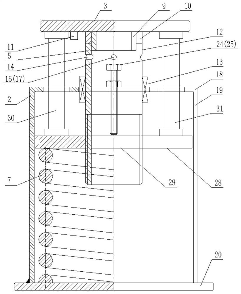
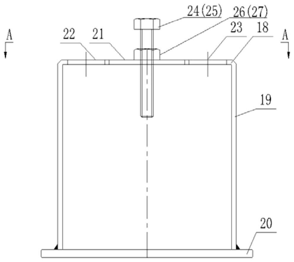
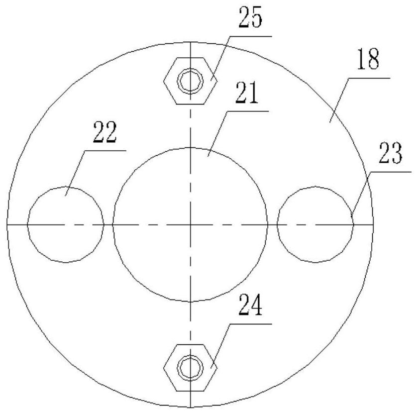
[0031] The present invention is described in further detail below in conjunction with accompanying drawing:

[0032] refer to Figure 1 to Figure 8 , the intelligent spring support system for easy debugging of the load according to the present invention includes a cover tube assembly 2, a cover plate assembly 3, a pillar 4, a data collection module 5, a first locking bolt 24, a second locking bolt 25 and an intelligent management Module 6; the cover tube assembly 2 includes a first cylinder 19, a top plate 18 fixed at the top opening of the first cylinder 19, and a bottom plate 20 fixed at the bottom opening of the first cylinder 19; the circular top plate 18 is provided with a second A round hole 21, a second round hole 22 and a third round hole 23, wherein the second round hole 22 and the third round hole 23 are respectively located on both sides of the first round hole 21, and the lower end surface of the spring 7 is fixed on the base plate 20 Above, the upper end of the s...


PUM


Abstract

The invention discloses an intelligent spring support system with a load convenient to debug. The intelligent spring support system comprises a cover cylinder assembly, a cover plate assembly, a supporting column, a data collection module, a first locking bolt, a second locking bolt and an intelligent management module. The cover cylinder assembly comprises a first cylinder, a top plate fixed to an opening in the top of the first cylinder and a bottom plate fixed to an opening in the bottom of the first cylinder. A first circular hole, a second circular hole and a third circular hole are formed in the circular top plate; the cover plate assembly comprises a disc, a cylindrical shaft sleeve, a cylindrical load sensor and a displacement sensor; and the supporting column comprises a second cylinder and a linear bearing. According to the system, the phenomenon that the spring support load column inclines can be avoided, load debugging is convenient and fast, the efficiency is high, and meanwhile loads and displacement can be accurately monitored in real time.

Description

technical field [0001] The invention relates to a spring support, in particular to an intelligent spring support system whose load is easy to debug. Background technique [0002] Spring support is an important load-bearing equipment for pipelines, tanks, valves, pumps and rotating machinery in power plants. Its load and displacement directly affect the safe operation of the equipment. Since the spring support does not require a large space for installation and suspension structures, the spring support has been widely used. Due to the structural characteristics of the traditional spring support, the support is often skewed and jammed. When the load of the spring support deviates from the design value, it is usually manual to use simple tools to rotate the support to achieve the purpose of roughly adjusting the load. Its disadvantages are as follows: (1) When the equipment supported by the spring support is not in the center of the support or when horizontal thermal displacem...

Claims


Application Information

Patent Timeline
Patent Type & Authority Applications(China)
IPC IPC(8): G01M13/00G01B21/02G01L5/00
CPCG01B21/02G01L5/0028G01M13/00
Inventor 陈盛广王军民王石军武彦飞李楠林王鹏
Owner XIAN THERMAL POWER RES INST CO LTD
Why Eureka
Eureka Blog
Learn More