

Data storage method and device, electronic equipment and storage medium
A data storage and data technology, applied in the computer field, can solve the problems of long response time and low concurrent utilization, and achieve the effect of improving concurrency efficiency and reducing response time.
- Summary
- Abstract
- Description
- Claims
- Application Information
AI Technical Summary
Problems solved by technology
Method used
Image

Examples
Embodiment 1
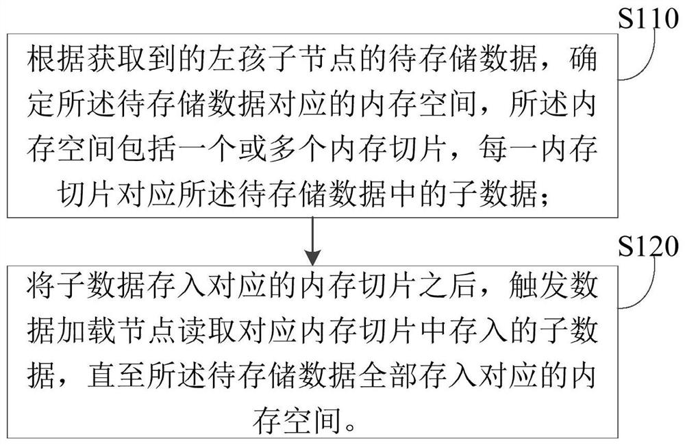
[0050] figure 1 It is a flow chart of a data storage method provided by Embodiment 1 of the present invention. This embodiment is applicable to the case where one or more sub-plans have a dependency relationship during execution. This method can be executed by a data storage device. The The device can be realized by means of software and / or hardware, and can be specifically inherited in an electronic device with storage and computing capabilities for data storage.
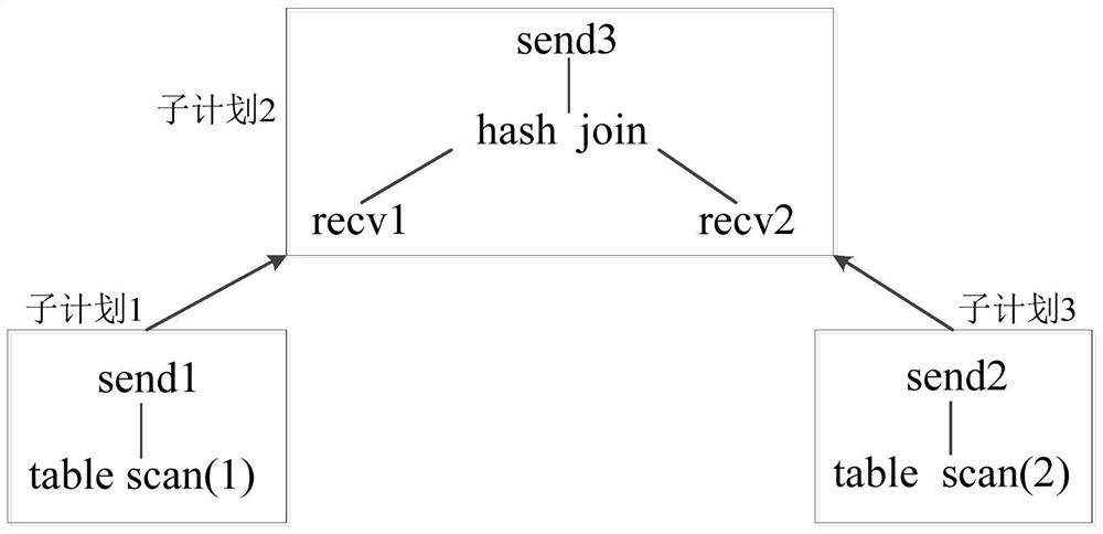
[0051]In the embodiment of the present invention, the parent plan can be understood as the parent node of the data storage node and the data loading node, and is used to schedule the data storage node and the data loading node to perform instruction operations. Among them, the data storage node and the data loading node are parallel sub-plans of the parent plan. The data storage node can be understood as a storage node or a data storage operator in a sub-plan in the parent plan, which is used to store correspondin...
Embodiment 2
[0089] figure 2 It is a flow chart of a data storage method provided by Embodiment 2 of the present invention. The technical solution of the embodiment of the present invention is further refined on the basis of the above technical solution, and is applied to the data loading node. The method specifically includes the following steps:
[0090] Step 210, obtaining the current access status of the data storage node;
[0091] In the embodiment of the present invention, the data loading node receives the data loading instruction sent by the parent plan according to the data loading requirement, so that the data loading node receives the data loading control authority of the parent plan. The data loading node performs corresponding data loading operations according to the data loading instructions sent by the parent plan. Before the data loading node performs corresponding operations, it needs to register with the corresponding data storage node before accessing.
[0092] Step 2...
Embodiment 3
[0107] image 3 It is a schematic structural diagram of a data storage device in Embodiment 3 of the present invention, which is applied to a data storage node, and the device includes:
[0108] The data storage module 310 is configured to determine the memory space corresponding to the data to be stored according to the acquired data to be stored of the left child node, the memory space includes one or more memory slices, and each memory slice corresponds to the to-be-stored data store subdata in the data;
[0109] The read trigger module 320 is configured to, after storing the sub-data into the corresponding memory slice, trigger the data loading node to read the sub-data stored in the corresponding memory slice until all the data to be stored is stored into the corresponding memory space.
[0110] Further, the data storage module 310 is specifically used for:
[0111] Determine the number of memory slices in the memory space corresponding to the data to be stored accordin...
PUM
 Abstract
Description
Claims
Application Information