Molded case circuit breaker

A technology of molded case circuit breaker and casing, which is applied to circuits, parts of protection switches, electrical components, etc., can solve the problems of inconvenient disassembly and assembly of plastic casings, poor heat dissipation effect, etc., so as to improve the protection effect, improve the heat dissipation effect, Effect of stable temperature environment

Pending Publication Date: 2021-03-12
BEIJING JINGSENYUAN ELECTRICAL APP CO LTD
View PDF10 Cites 1 Cited by
  • Summary
  • Abstract
  • Description
  • Claims
  • Application Information

AI Technical Summary

Problems solved by technology

[0005] In order to solve the technical problems of inconvenient disassembly and assembly of the plastic case and poor heat dissipation effect of the plastic case circuit breaker in the prior art, the present invention provides a molded case circuit breaker

Method used


Image

  • Molded case circuit breaker
  • Molded case circuit breaker
  • Molded case circuit breaker

Examples


Embodiment 1

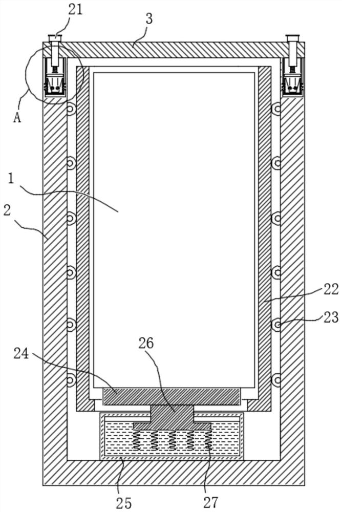
[0035] Please combine Figure 1 to 3 The molding case circuit breaker includes a plastic case circuit breaker body 1, and the outer cover of the plastic case circuit breaker main body 1 is provided with a housing 2, and the outer cover of the molding case circuit breaker main body 1 is provided with a housing 2, and the housing 2 is reserved. The beam line passing through the harness of the shell circuit breaker main body 1 (not shown). One end of the housing 2 has an insertion port (not indicated) inserted from the plastic shell circuit breaker main body 1, and the housing 2 is provided with a housing cover 3 for closing the insertion. Through the housing 2 and the shell cover 3, the plastic case circuit breaker main body 1 can be improved to avoid the operation of the external environment affects the molding circuit breaker.

[0036] The housing cover 3 is disposed on one side of the housing 2 with an interior hollow adapter block 5, and the housing 2 is opened, and the adapter ...

Embodiment 2

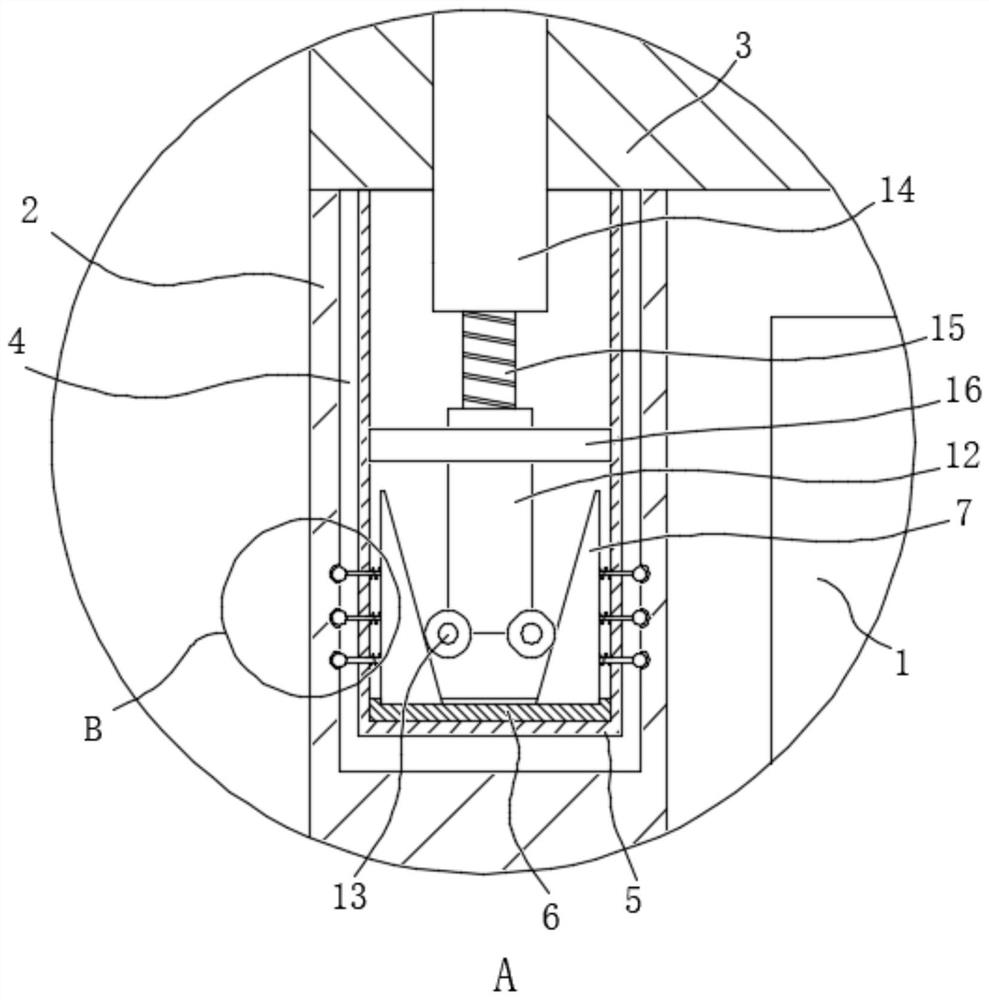
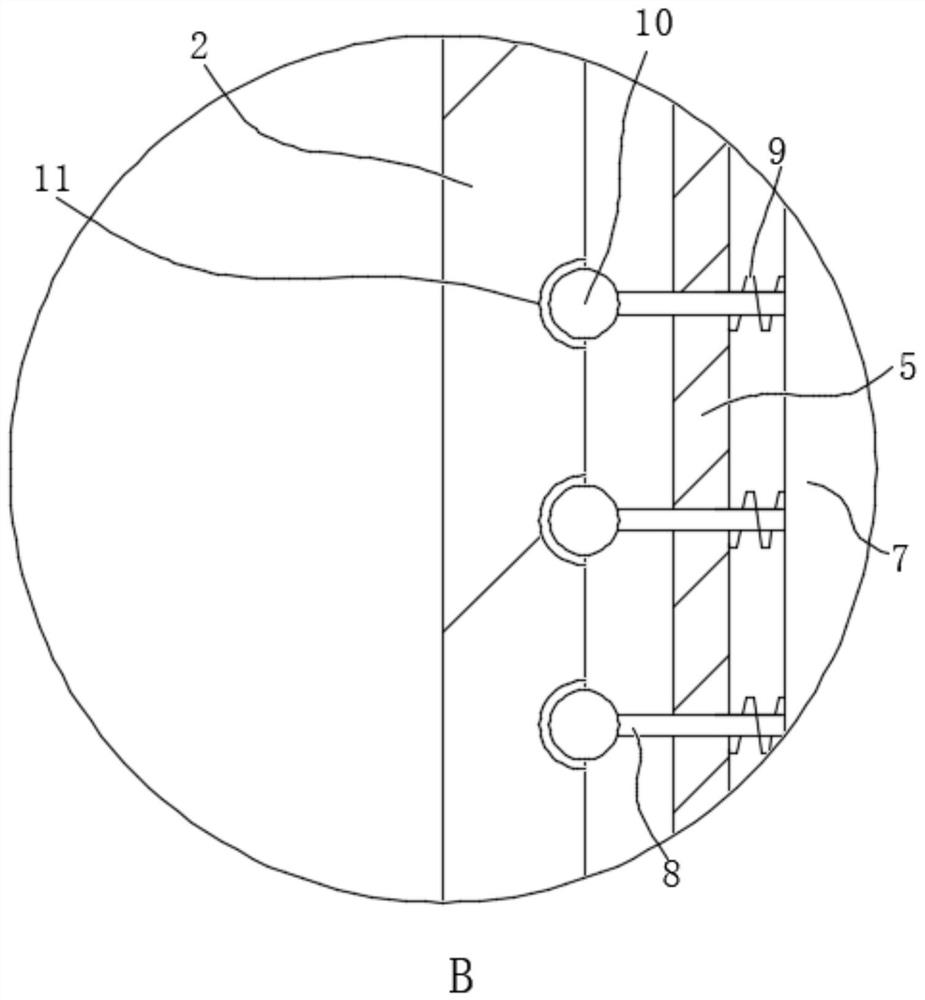
[0052] Please combine Figure 4 to 6 The present embodiment is an improvement scheme of Example 1. Specifically, both sides of the casing 25 are provided with a pair of linked seats, and each of the pair of receiving grooves 30, the carrier cartridge 22 facing the box 25 One side is provided with a pairing block 28 that cooperates with the tang 30, and between the pair of pieces 28 and the pairing groove 30 are engaged. The carrier cartridge 22 can be more smooth and reliable by the engaging of the pair of ligated grooves 28 and the pair of ligated blocks 28, and the launch of the carrier 22 can be more smooth and reliable.

[0053] A bead groove 28 is opened on the block 28, and the top beads 33 are connected by the spring die 33 in the bead tank 34, and the top groove 2 31 that cooperates with the top beads 2 32 is opened. Among them, when the spring 23 does not have a deformation, the pending 32 of the pending die 32 is flat to the slots of the bead groove one 34.

[0054] When ...


PUM


Abstract

The invention relates to the technical field of circuit breakers, and discloses a molded case circuit breaker. The circuit breaker comprises a molded case circuit breaker body, a shell covers the outer side of the molded case circuit breaker body, an insertion opening is formed in one end of the shell, a shell cover is arranged on the shell, a connecting block is arranged on the side, close to theshell, of the shell cover, and a connecting groove is formed in the shell; the connecting groove and the connecting block are locked and fixed through a locking mechanism; a box body is arranged at the end, away from the insertion opening, in the shell, and cooling liquid is contained in the box body. A heat conduction assembly is arranged on the side, facing the insertion opening, of the box. The heat conduction assembly is used for conducting heat generated by the molded case circuit breaker main body to the cooling liquid. The shell and the shell cover are connected through the connectinggroove and the connecting block, the locking mechanism is additionally arranged on the basis, rapid disassembly and assembly between the shell and the shell cover are achieved, the disassembly workload of workers is greatly reduced, meanwhile, the heat conduction assembly and the box body are additionally arranged in the shell, and the heat dissipation effect is improved; and a stable temperatureenvironment is provided for normal operation of the molded case circuit breaker.

Description

Technical field [0001] The present invention relates to the field of circuit breaker, and more particularly to a plastic case circuit breaker. Background technique [0002] In the electrical product exhibition and electrical market, the low-voltage circuit breaker can be seen everywhere, especially the plastic cutting circuit breaker. The plastic cutting circuit breaker has two-stage protection function of overload long delay, short-circuit transient, and can also be used in conjunction with a leakage, measurement, and electromically operated module unit. In the low voltage power distribution system, it is common to do a terminal switch or a branch switch, replacing the previously used fuse and the knife switch. [0003] The plastic case circuit breaker is also referred to as a device-type circuit breaker, and the mold cutter is to put the contacts, arc extinguishing devices, trippers, and operating mechanisms in a plastic housing, generally not considering repair, use and budget...

Claims


Application Information

Patent Timeline
Patent Type & Authority Applications(China)
IPC IPC(8): H01H71/02H01H9/52
CPCH01H71/0264H01H71/02H01H9/52
Inventor 薛明亮黄凌志崔高鹏刘征黄立强
Owner BEIJING JINGSENYUAN ELECTRICAL APP CO LTD
Why Eureka
Try Eureka