Supercharge Your Innovation With Domain-Expert AI Agents!

Method for reducing input power frequency ripples

A ripple and input power technology, applied in the field of reducing input power frequency ripple, can solve problems such as inability to guarantee aging and affect product production, and achieve the effect of guaranteeing normal aging and reducing input power frequency ripple

Active Publication Date: 2021-03-12
SHENZHEN ZHONGKEYUAN ELECTRONICS
View PDF6 Cites 0 Cited by
  • Summary
  • Abstract
  • Description
  • Claims
  • Application Information

AI Technical Summary

Problems solved by technology

Excessive ripple current will cause the DC power supply to trigger overvoltage, overcurrent or overpower protection during the aging process, which cannot guarantee normal aging and affects product production

Method used


Image

  • Method for reducing input power frequency ripples

Examples


Embodiment 1

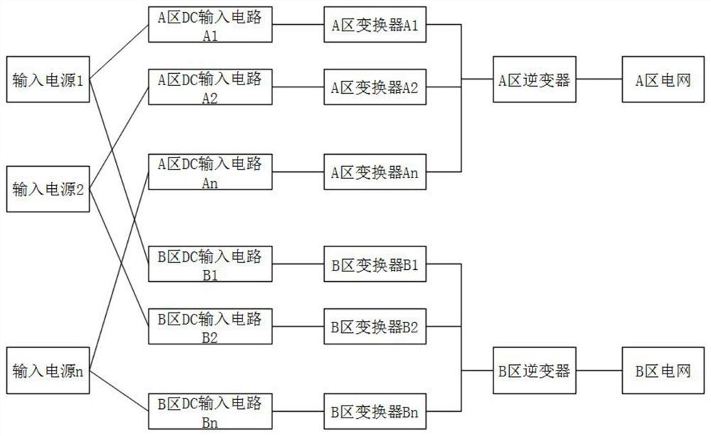
[0036] When the two DC inputs are connected in parallel, in the present invention, one DC-DC conversion circuit connected to the power grid in area A and one DC-DC conversion circuit connected to the power grid in area B are selected instead of the traditional two-way DC-DC conversion circuit connected to the same phase of the power grid. DC-DC conversion circuit. Because there is a fixed phase difference between the power grid in area A and the power grid in area B, the input power frequency ripple of the two DC-DC conversion circuits also has a fixed phase difference, and the input power frequency ripple after the two are connected in parallel will be significantly reduced. Assume that the input power frequency ripple of each DC-DC conversion circuit is K sinωt, that is, the peak-to-peak value of each input power frequency ripple is 2K, if connected to the same phase of the power grid, the input power frequency ripple after parallel connection is K sinωt, that is, the peak-t...

Embodiment 2

[0038] When there are three or more DC-DC conversion circuit inputs connected in parallel, if the number of parallel circuits is an integer multiple of three R, the input power frequency ripple after parallel connection is R·(K·sinwt+K·sin(120+ ωt)+K·(ωt+240))=R×0=0, that is, the peak-to-peak value of the input ripple after parallel connection is 0; After parallel connection, the input ripple is 0, and the input ripple of the remaining channel is not canceled, then the ripple expression after parallel connection is K sinωt, that is, the peak-to-peak value of the input power frequency ripple after parallel connection is 2K; if When the number of parallel circuits is not an integer multiple of three, and the remainder is 2, since the input ripple is 0 after the integer multiple of 3 is connected in parallel, the input ripple of the remaining 2 channels is not canceled out, and the ripple expression after parallel connection is The formula K·sinωt+K·sin(120°+ωt)=K·sin(ωt-120°), t...


PUM


Abstract

The invention discloses a method for reducing input power frequency ripples. The method comprises the following steps of (1) setting a power grid input system which comprises input power supplies withthe numbers of 1-n, A-region converters with the numbers of A1-An and B-region converters with the numbers of B1-Bn, wherein an A-zone DC input circuit and a B-zone DC input circuit with the corresponding numbers are connected between each input power supply and the A-zone converter and the B-zone converter with the corresponding numbers to form a corresponding DC-DC conversion circuit; (2) accessing in a power grid inverter system, wherein the power grid inverter system comprising an A-zone inverter and a B-zone inverter, the output ends of all A-zone converters are connected in parallel andthen are accessed to the A-zone inverter, the output ends of all B-zone converters are connected in parallel and then are accessed to the B-zone inverter, the output end of the A-zone inverter is accessed to an A-zone power grid, and the output end of the B-zone inverter is accessed to a B-zone power grid; and (3) connecting the A-region power grid and the B-region power grid to a circuit load, and electrifying an input power supply for operation.

Description

technical field [0001] The invention relates to the technical field of power electronics, in particular to a method for reducing input power frequency ripple. Background technique [0002] In order to be more flexible for the aging of DC power supplies with different powers, generally the power of each DC input is small, so that more low-power DC power supplies can be aged at the same time. When aging a high-power DC power supply, multiple DC inputs are connected in parallel. , increase the input power to ensure full power aging of the DC power supply. In the process of application, the DC input has power frequency ripple, because multiple DC inputs are applied in parallel, and the input power is greater, so the power frequency ripple is larger. Excessive ripple current will cause the DC power supply to trigger overvoltage, overcurrent or overpower protection during the aging process, which cannot guarantee normal aging and affects product production. The invention propose...

Claims


Application Information

Patent Timeline
Patent Type & Authority Applications(China)
IPC IPC(8): H02M1/14H02M1/32H02J1/10H02J3/38
CPCH02M1/14H02M1/32H02J1/10H02J3/38
Inventor 徐立平黄恒华吴涛
Owner SHENZHEN ZHONGKEYUAN ELECTRONICS
Features
  • R&D
  • Intellectual Property
  • Life Sciences
  • Materials
  • Tech Scout
  • Unparalleled Data Quality
  • Higher Quality Content
  • 60% Fewer Hallucinations
Learn More